
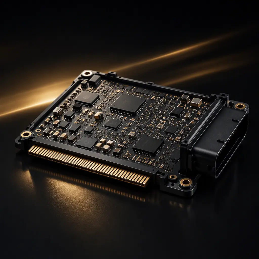
Automotive Ethernet replaced CAN and LIN in the networks where bandwidth matters: surround-view cameras, radar and LiDAR pre-processing, infotainment displays, and the zonal gateways that aggregate everything. Unlike office Ethernet it runs over a single twisted pair at 100 Ω differential impedance with no magnetics, no RJ45, and no cable that a human can swap. The link budget is fixed at design time and the PCB is responsible for a large share of it. At 1000BASE-T1 the symbol rate is 750 MBd, which puts every via, stub and impedance discontinuity inside the ECU under the same scrutiny that PCIe Gen3 routing receives.
This guide explains what changes when you design a board around an automotive Ethernet PHY: the physical-layer standards and what they demand from the layout, the 100 Ω differential discipline, common-mode choke and PoDL filtering, CISPR 25 EMC in a module environment, connector selection, and the manufacturing verifications that separate a first-pass-clean ECU from a compliance failure. Huaxing PCBA builds automotive boards under IATF 16949 with ±5% impedance capability and sees both outcomes regularly, the failures are almost never the silicon. For the legacy networks that still share the vehicle, our CAN bus PCB design guide covers the differential pair rules for the rest of the harness.
Why Automotive Ethernet Is Not Office Ethernet
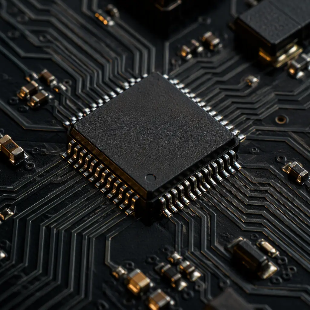
The differences are structural, not cosmetic. Standard Ethernet uses two pairs (or four), requires isolation magnetics, and is designed around structured cabling with defined patch panels. Automotive Ethernet uses one pair, full duplex on that pair, and replaces the transformer with a common-mode choke, which also saves the ~2.5 cm of board area a magnetics module occupies and removes the coupling capacitor tuning that plagues RJ45 designs.
| Parameter | Office Ethernet (100BASE-TX) | Automotive 100BASE-T1 | Automotive 1000BASE-T1 |
|---|---|---|---|
| Pairs used | 2 (TX + RX) | 1 (echo-cancelled) | 1 (echo-cancelled) |
| Symbol rate | 125 MBd | 33.3 MBd | 750 MBd |
| Line code | MLT-3 | PAM3 | PAM3 |
| Link segment | 100 m, 4 connectors | 15 m, 2 in-line connectors | 15 m, 4 in-line connectors |
| Isolation | Magnetics + CM choke | Common-mode choke | Common-mode choke |
| Differential impedance | 100 Ω | 100 Ω ±10% | 100 Ω ±10% |
| Standard | IEEE 802.3u | IEEE 802.3bw / OPEN Alliance TC1 | IEEE 802.3bp / OPEN Alliance TC12 |
Because there is only one pair, the PHY uses echo cancellation to transmit and receive simultaneously on the same wires. That makes the interface inherently more sensitive to impedance discontinuities than a four-pair design where reflections add to an already busy return path. The practical consequence: the 100 Ω differential pair between PHY and connector is a controlled-impedance element from the first pad to the last, and every deviation is shared by both directions of traffic.
Key Takeaway: If your team has only routed office Ethernet, forget everything the magnetics taught you. Automotive Ethernet is a single-pair 100 Ω system with no transformer. The common-mode choke placement and the connector launch are the two spots where most first-pass boards lose compliance margin.
The 100 Ω Differential Discipline: Routing the PHY to the Connector
The OPEN Alliance TC2 channel specification defines the allowed insertion loss, return loss and mode conversion for the full link between two PHYs. The PCB portion: typically 50–200 mm inside the ECU. Must hold 100 Ω differential impedance within ±10%, and for 1000BASE-T1 designs targeting the full 15 m link the trace loss contribution must stay well under the channel budget.
Keep the pair short and on one layer
Aim to route PHY-to-connector pairs as direct as the enclosure allows, with no more than two layer changes. Every via pair adds roughly 0.2–0.4 dB of insertion loss at 375 MHz (the 1000BASE-T1 Nyquist) plus a stub that resonates near the upper edge of the band. If a layer change is unavoidable, transition both traces at the same point with mirrored vias and back-drill anything that extends beyond the target layer.
Control intra-pair skew tightly
At 750 MBd the bit time is 1.33 ns and the PAM3 eye is dense. Keep intra-pair length mismatch below 5 mil (0.13 mm). Do not route one side of the pair through an extra via or around a mounting hole while the other side goes straight. The skew budget you spend on the PCB is taken directly from the cable budget.
Guard against aggressors and return-path breaks
Keep the pair at least 3× the dielectric height away from parallel clocks, switching regulators and other differential pairs. Never route over a slot or split in the reference plane. The return current needs an unbroken ground directly beneath. For pairs running the length of the board, add stitching vias along the ground pour beside the pair.
Place the PHY close to the connector
PHY-to-connector distance is the single largest PCB loss contributor. In a zonal gateway routing six pairs, spread the connectors along the board edge closest to the PHY array instead of fanning all six across the board. Shortest possible trace wins; the impedance control guide explains how to target 100 Ω ±10% with the right trace width and dielectric spacing on your chosen stackup.
Common-Mode Chokes, ESD and PoDL Filtering
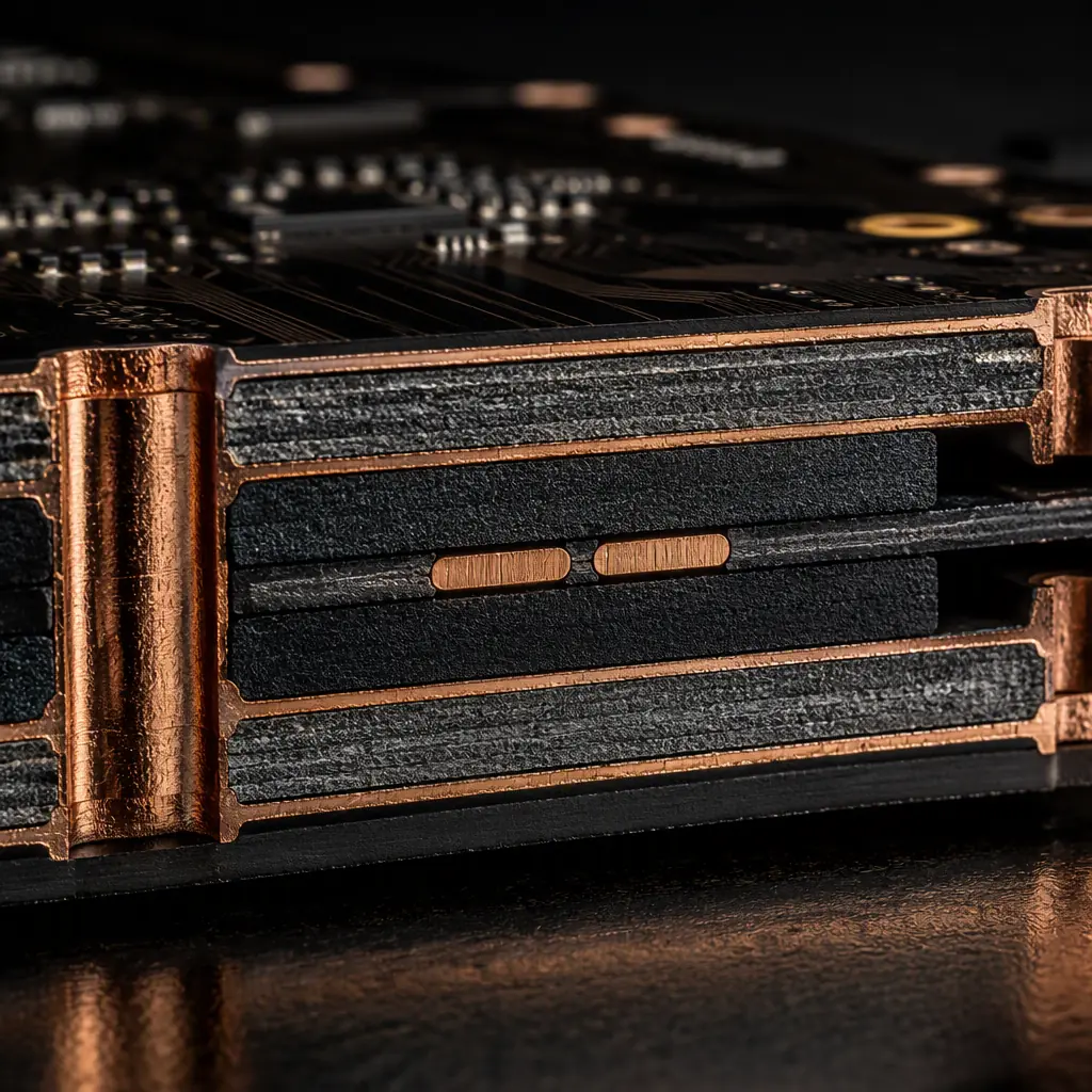
The common-mode choke (CMC) is the automotive replacement for the isolation transformer. It passes the differential signal almost unchanged while presenting high impedance to common-mode noise. Which is exactly what the PHY couples onto the pair and what the pair picks up from the vehicle environment. A typical 100BASE-T1/1000BASE-T1 CMC is a 1:1 device with a common-mode impedance of 90 µH at 100 MHz, chosen to block emissions from 1 MHz up to the 1 GHz radiated test band.
Put the choke between the PHY and the connector
The CMC must sit in the differential path after the PHY AC-coupling caps and before the connector, as close to the connector as the layout allows. Keep the choke's pads on the 100 Ω geometry. The small impedance bump at the choke is acceptable, but the stubs to its pins are not.
Add ESD protection rated for automotive transients
ISO 7637-2 transients and ESD per ISO 10605 can reach several kilovolts at the connector. Use a low-capacitance (< 1 pF) TVS array between the pair and chassis ground, placed between the CMC and the connector so the clamp happens before the choke. Verify the TVS capacitance at the operating frequency — an automotive-rated TVS that adds 2 pF per line can eat 0.5 dB of return-loss margin at 750 MBd.
Filter PoDL separately from the data pair
Power over Data Lines (IEEE 802.3bu) feeds 12 V, 24 V or 48 V onto the same pair through steering inductors, with classes up to roughly 60 W. The power feed inductors must be placed so their magnetic field does not couple into the differential pair, and the PoDL filter caps need a solid connection to the module's power return. Mixing the PoDL ground with the data reference ground at the choke is a common source of mode conversion.
EMC: Passing CISPR 25 in a Module Environment
Automotive modules are qualified against CISPR 25 radiated and conducted emissions and ISO 11452 immunity, measured with the ECU, harness and load box on a bench. Unlike a lab-friendly office switch, the ECU sits centimeters from antennae, high-voltage cabling and the vehicle's own transmitters. Three layout habits decide whether the Ethernet port passes on the first bench run:
Keep the pair inside a reference boundary
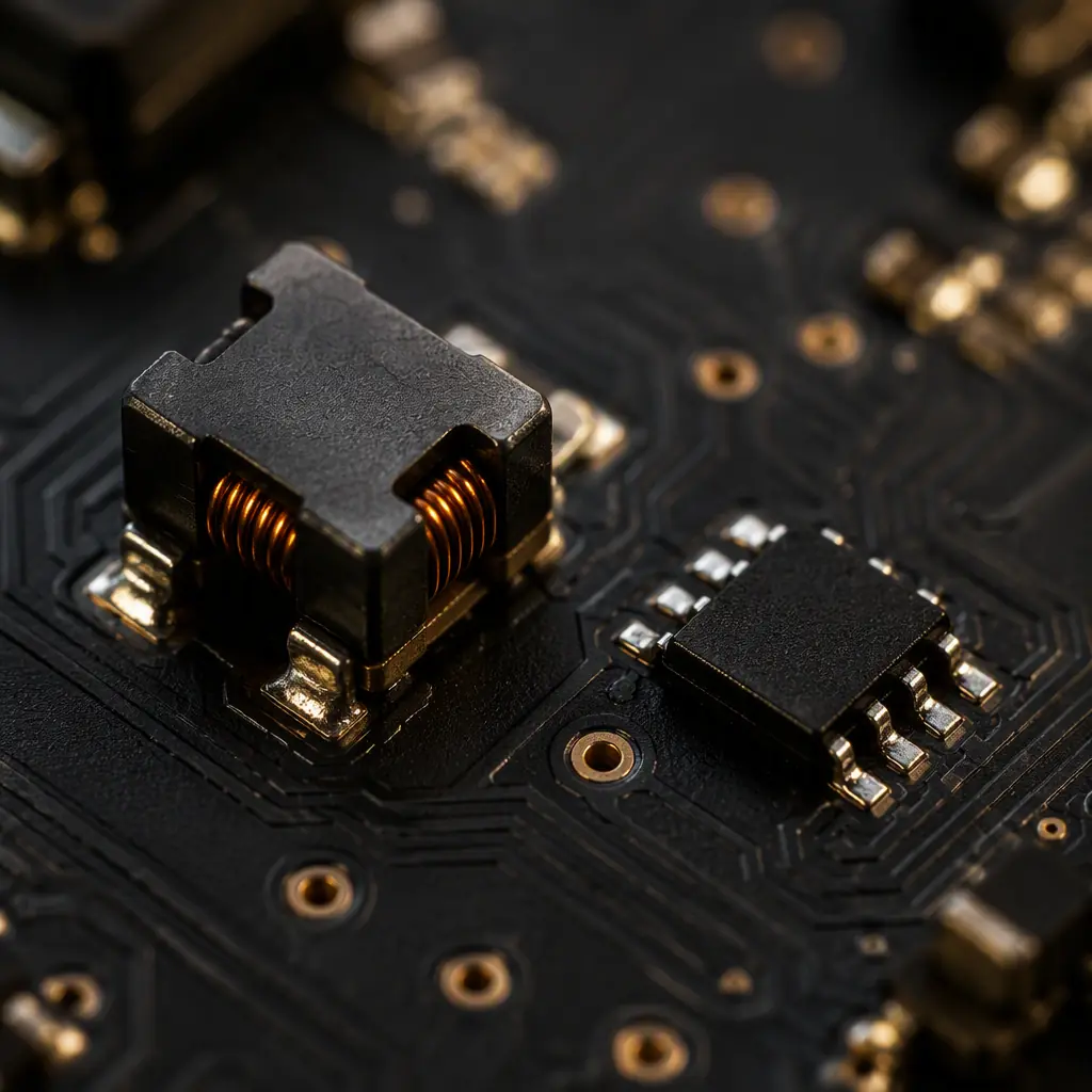
Route the differential pair on an internal layer with ground above and below wherever possible. A pair exposed on the outer layer with the chassis seam or a plastic housing nearby radiates like an antenna at the PAM3 harmonics. Edge plating and ground stitching around the connector area contain the field.
Use spread-spectrum and slew-rate control
Most automotive PHYs support spread-spectrum clocking (±0.5% or ±0.25% down-spread) and programmable slew rate. Enabling both reduces peak emissions by several dB at the source, cheaper than any board-level fix applied later. Specify the PHY configuration in the design notes so firmware and hardware teams agree before the EMC lab.
Connect the shield, if the cable has one
1000BASE-T1 links frequently use shielded twisted pair (STP) to meet CISPR 25 with margin. The connector's shield termination must land on the module ground with a low-impedance path, a dedicated ground pad under the connector, not a long pigtail to a via 10 mm away. The PCB EMC/EMI compliance guide covers the general enclosure and filtering strategy for automotive modules.
Connector Selection: H-MTD, HSD and FAKRA-Style
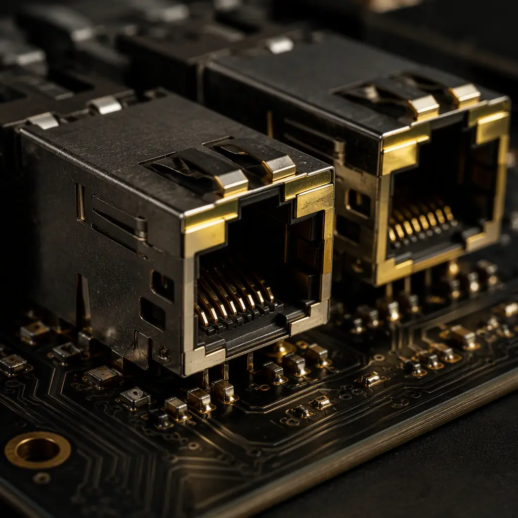
The connector family determines the launch geometry, the shield strategy and the mechanical retention. And it must be chosen before layout, not after. The three automotive Ethernet connector families in production today:
| Connector | Typical Data Rate | Pairs | Where You See It |
|---|---|---|---|
| H-MTD (Rosenberger) | Up to 20+ Gbps capable | 1–2 | 1000BASE-T1, cameras, zonal gateways |
| HSD (TE, Molex) | Up to 2 Gbps per pair class | 1–2 | Infotainment, displays, 100BASE-T1 |
| Mini-FAKRA / USCAR-2 style | 100BASE-T1 class | 1 | Entry ECUs, sensors, low-cost links |
Each family has a defined PCB footprint, recommended keep-out and shield termination pad. Order the connector's evaluation board layout or footprint recommendation from the vendor before routing. The differences between the H-MTD and HSD launch geometries are enough to shift the return loss by 2–3 dB at 750 MBd. For 1000BASE-T1, plan for the connector's 4 in-line connectors allowance across the full 15 m link, and keep the PCB-side loss under about 1 dB so the cable and the four connector pairs stay inside the TC2 budget.
Manufacturing Verification: What to Demand From the Fab
Automotive Ethernet boards fail compliance for manufacturing reasons as often as design reasons, impedance that drifts out of the ±10% window, etch that widens the pair asymmetrically, or a via stub left by an inconsistent back-drill. These are the verifications to put in the fabrication notes and the incoming inspection plan:
Impedance coupons on every panel, TDR-verified
Require a 100 Ω differential coupon on every panel and a TDR report from the fab before release. A coupon-only pass is not enough. Request the actual trace width and dielectric thickness measurements that produced the impedance, and keep the tolerance at ±10% minimum, ±5% where the link runs the full 15 m. See our manufacturing tolerances guide for what is realistic to hold.
Back-drill verification for high-layer-count boards
If the stackup uses blind vias or back-drilled vias in the Ethernet path, add an x-ray or cross-section check of the remaining stub length. The stub allowance for 1000BASE-T1 is small, beyond ~150 µm of remaining stub the resonance moves into the band. Our back drilling guide covers the stub math.
Require IATF 16949 process controls and full traceability
Automotive OEMs and Tier-1s expect PPAP-level documentation: material certs, solder paste lot records, reflow profiles, AOI and x-ray results per board, and serialized traceability. If your supplier cannot produce an IATF 16949 certificate and a PPAP package, the ECU will be requalified at every customer audit. The PPAP for PCB assembly guide lists the 18 elements to request.
Material choice: Tg 170 for underhood, standard FR-4 elsewhere
Cabin electronics can use conventional FR-4 (Tg 140–150); powertrain and underhood ECUs need Tg 170 laminates to survive 125 °C ambient with 150 °C hotspots. The dielectric constant of Tg 170 materials varies less over temperature, which also stabilizes the impedance across the operating range, relevant when the link budget is tight.
Building an Automotive Ethernet ECU That Passes First Time
Design the channel before you place a single component: fix the connector family, the PHY, the choke and the TVS, then allocate the loss budget between PCB, connector and cable. Route the pair as a 100 Ω transmission line with controlled skew, keep the choke and ESD on the connector side, filter PoDL away from the data path, and verify impedance and back-drill quality at the fab. That sequence produces links that train at 1000BASE-T1 speed and pass CISPR 25 with margin, the same sequence our customers' failed boards skipped in a different order.
At Huaxing PCBA we fabricate automotive boards up to 32 layers with ±5% impedance control under IATF 16949, and we assemble them with serialized traceability and full PPAP documentation across 8 SMT lines. Read our automotive PCB requirements guide for the full qualification checklist, or send your Gerbers for a DFM review and a quote with the impedance and back-drill verification included.
