
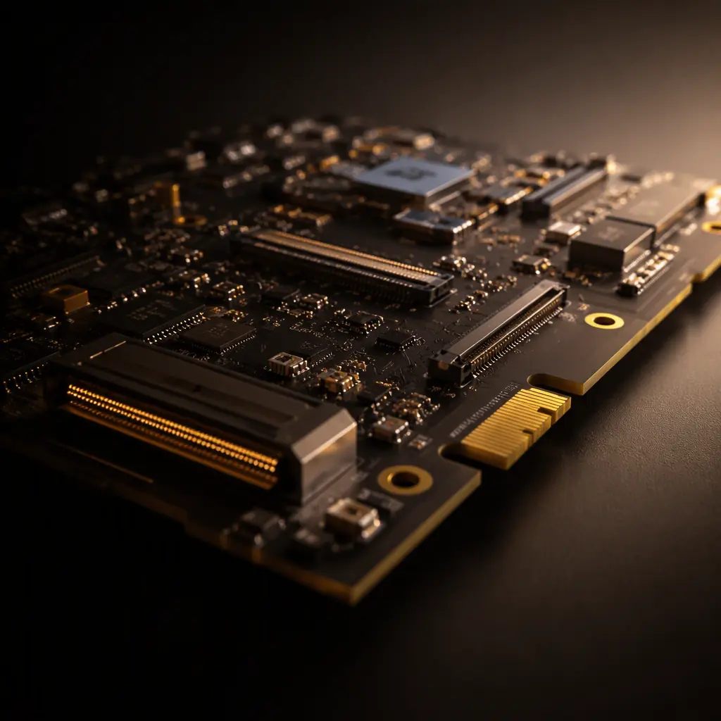
Modern vehicles ship with a digital cockpit: a cluster, a center information display, sometimes a passenger display and head-up display, all driven by a system-on-chip that rivals a laptop in complexity. The PCBs behind these screens combine high-speed digital interfaces, power electronics, audio, and wireless modules on boards that must survive −40°C cold starts, 85°C dashboards, vibration, and a 15-year design life under AEC component rules.
Huaxing PCBA builds cockpit and infotainment boards for Tier-1 and Tier-2 automotive suppliers — up to 32 layers, with HDI microvia stacks, controlled impedance, and IATF 16949 process controls. This guide covers the interfaces you will route, the EMC budget you must hold, and the manufacturing choices that separate an automotive board from a consumer board. For the general requirements of automotive electronics, start with our automotive PCB requirements guide.
Why Cockpit Boards Are Not Consumer Boards
The most common procurement mistake is treating a head unit like a tablet PCB. The differences are structural, not cosmetic. Every component must be an automotive-grade part (AEC-Q100 for ICs, AEC-Q200 for passives), the board must survive thermal cycling from −40°C to +85°C for thousands of cycles, and every electronic function must be traceable under IATF 16949. The consequences of a field failure — a recall — cost orders of magnitude more than the board itself.
| Attribute | Consumer Board | Automotive Cockpit Board |
|---|---|---|
| Component grade | Commercial | AEC-Q100 / Q200, PPAP |
| Temperature range | 0–60°C | −40–85°C (grade 2), up to 105°C (grade 0) |
| Design life | 2–3 years | 10–15 years |
| EMC requirement | FCC Class B | CISPR 25 Class 3–5, ISO 7637 transients |
| Traceability | Lot level | Single-board level (UID marking) |
| Vibration | None specified | ISO 16750-3, 10–1000 Hz |
The stackup decision follows directly from the reliability requirement. Automotive boards favor thicker copper and controlled dielectric systems over exotic ultra-thin laminates. Our PCB stackup design guide and laminate selection guide cover the material trade-offs in detail.
The Display Interface Zoo: LVDS, MIPI DSI, eDP, and SerDes
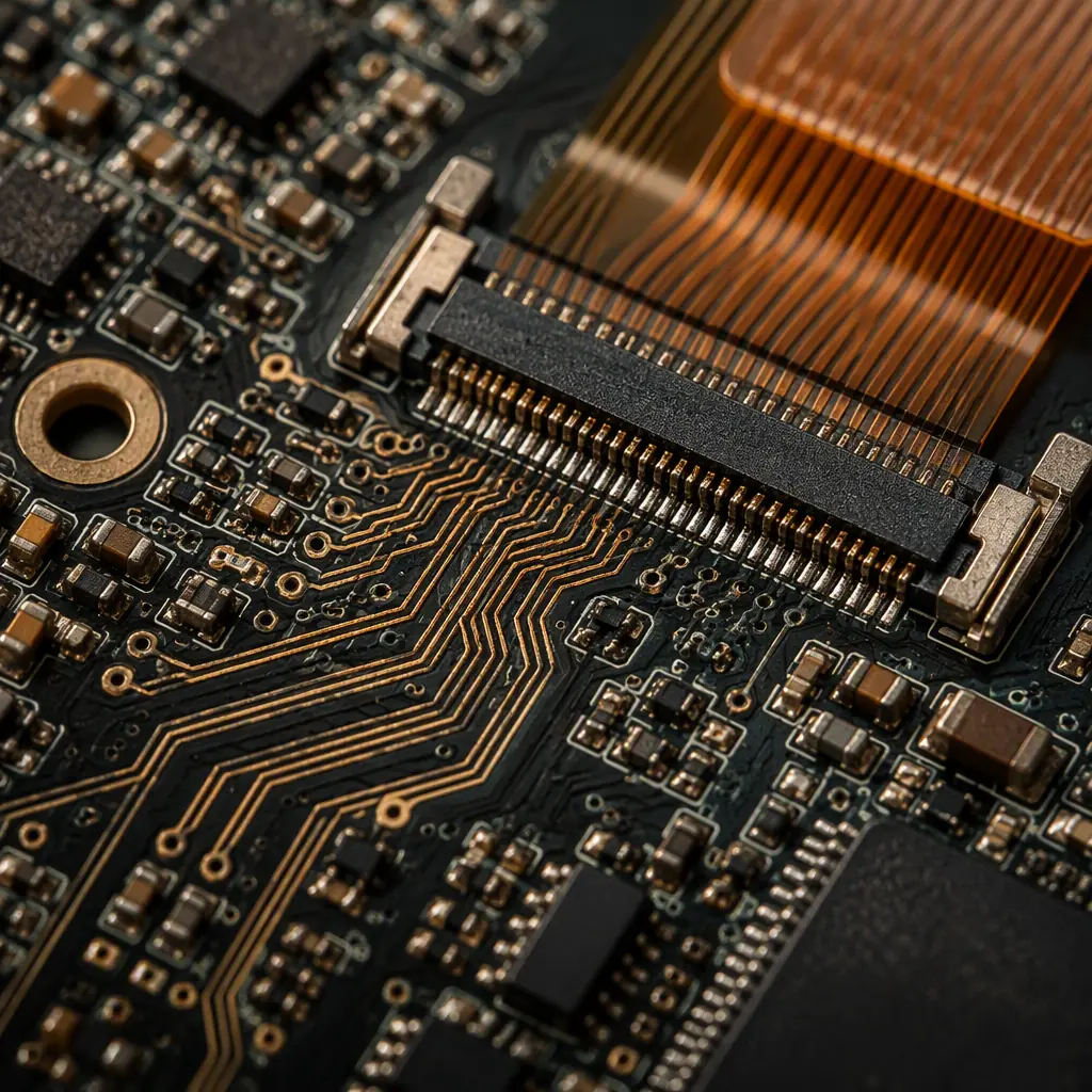
A single cockpit aggregates every display interface in the industry. The cluster typically uses LVDS or MIPI DSI; the center display uses eDP or GMSL; the head-up display and cameras use automotive SerDes (GMSL, FPD-Link). Each interface has its own impedance, voltage, and routing discipline — and many boards carry all of them at once.
| Interface | Differential Impedance | Typical Speed | Typical Use |
|---|---|---|---|
| LVDS | 100 Ω | 0.5–3 Gbps | Cluster, legacy displays |
| MIPI DSI | 100 Ω (pairs) | 1.5–4.5 Gbps/lane | Touch displays, small panels |
| eDP | 100 Ω | Up to 8.1 Gbps/lane | High-res center displays |
| GMSL / FPD-Link | 100 Ω | Up to 6 Gbps | Camera, long-reach links |
Routing discipline for all of these is the same at the board level: controlled 100 Ω differential pairs, length matching within the lane group, solid reference plane, and no vias in the pair unless both signals transition together. For the detailed rules, our signal integrity guide and impedance control guide cover pair routing, via transitions, and coupon requirements.
Length-Match Within the Lane, Not Just the Pair
MIPI and LVDS specify skew between lanes. Match lengths within a few mils across the whole lane group, not just within one pair. Most layout tools do this automatically once the constraint is set — but the constraint is often forgotten on mixed-interface boards.
Keep Display Links Off the Power Plane Edges
The switching noise from the DC-DC converters in the cockpit couples into long display routes that run near plane edges. Route the high-speed lanes over solid reference, away from the power stage. Our crosstalk analysis guide quantifies the coupling.
Plan SerDes for a Single Connector Transition
Automotive SerDes links run meters of cable, so the PCB side must be clean. Keep the serializer close to the connector, use a ground stitch around the connector footprint, and never route the pair through a split plane. Our high-speed board guide shows the connector-zone layout pattern.
EMC: Holding CISPR 25 Class 3–5 in a Metal Box
Infotainment is the noisiest subsystem in the vehicle: switching regulators, high-speed display clocks, and wireless radios all share one board. The OEM EMC requirement is typically CISPR 25 radiated emissions Class 3 to Class 5 depending on the frequency band, plus ISO 7637 transient immunity on the power input.
Budget the Switching Regulators Early
Each buck converter is an intentional noise source. Spread them across the board rather than clustering them, keep their switching loops tight, and route their outputs away from display lanes. The EMC and EMI compliance guide covers loop-area control and filtering.
Shield the Display Clock Sources
Display clocks and their harmonics sit in FM and DAB radio bands. A grounded shield over the clock area, or a ground pour with stitching vias around it, usually recovers 5–10 dB of margin. Our EMC design rules include the shield-placement checklist.
Filter the Power Input for ISO 7637
The 12 V rail carries load-dump and transient spikes. A TVS array plus an input LC filter at the connector is the minimum; verify the filter's resonance is damped so it does not ring at the OEM test pulse. Our power integrity guide covers input filtering design.
Thermal and Mechanical: The Cockpit Is a Heater
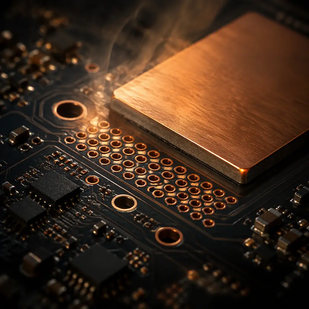
A center display SoC can dissipate 5–10 W, inside a dashboard that already exceeds 60°C on a sunny day. The board itself must conduct that heat to the enclosure, which means thermal vias under the SoC, copper planes that carry heat laterally, and careful placement of the regulators that add their own dissipation. Warpage control matters equally: a cockpit board with a large SoC and mixed thicknesses can bow during reflow and fail connector coplanarity.
Design the Thermal Path to the Enclosure
Thermal vias under the SoC and regulators, tied to planes that reach a board-edge pad contacting the metal housing, turn the dashboard into a heatsink. Our thermal management guide has the via-array sizing formulas.
Balance Copper for Warpage
Symmetric stackups and balanced copper pours across layers prevent bow and twist after reflow. For large cockpit boards, keep the copper density within 10% between mirrored layers. Our warpage prevention guide covers the stackup and panelization rules.
Plan for Vibration at the Connector
The board-to-board and board-to-cable connectors take the worst vibration load. Add mounting holes near heavy connectors and use stiffeners on long flex tails. The vibration testing guide explains the qualification tests.
Manufacturing: HDI, Microvias, and Process Control
The cockpit board's density demands HDI construction: microvias, buried vias, and often 4–6 sequential laminations. That is where manufacturing capability separates automotive-capable suppliers from board houses that only do standard through-hole stacks. The HDI technology guide covers the stackup options; here are the procurement-level checks.
Verify Microvia Reliability Data
Automotive thermal cycling stresses microvias hard. Ask for IPC-6012 qualification data and IST results, not just a capability statement. Our microvia reliability guide lists the exact questions to ask.
Confirm 100 Ω Coupon Coverage
Every impedance net group needs coupons measured against your target. Do not accept "designed to 100 Ω" — accept measured values from the production panel. The impedance control guide has the coupon template.
Check the Surface Finish for Mixed Needs
ENIG for the fine-pitch SoC and connector pads, plus selective OSP or ENEPIG where wire bonding appears. A single finish across the board usually forces a compromise. Our surface finish selection guide walks through the options.
Require PPAP for the Module
For production cockpit modules, the supplier should submit PPAP with control plans, FMEA, and capability data. The PPAP guide for PCB assembly lists the 18 elements and what each should contain.
Summary: Design for the Recall, Not the Demo
A cockpit board that looks great in the demo vehicle fails in the field when the display clock radiates into the FM band, the SoC overheats on a summer day, or a microvia cracks after two years of thermal cycling. The design rules are known: AEC-grade parts, disciplined high-speed routing, an early EMC budget, a real thermal path, and HDI construction from a supplier with automotive process controls.
At Huaxing PCBA, we manufacture automotive infotainment and cockpit boards under IATF 16949, with HDI up to 32 layers, controlled impedance, single-board traceability, and PPAP support. Read our automotive requirements guide for the complete qualification checklist, or send your stackup and layout for a DFM review focused on cockpit-specific risks before tooling.
