
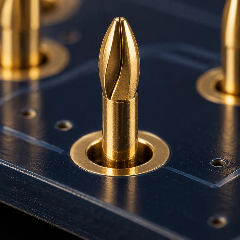
Press-fit connectors are the least glamorous way to attach a backplane, and the most reliable. No solder joint, no thermal excursion, no flux residue under a 500-pin array. Instead a compliant pin is forced into a plated through-hole and the interference fit creates a gas-tight cold weld that survives vibration, thermal cycling and 30 years of service. The catch is that the entire joint is created by the hole and the pin meeting within a few tens of microns of tolerance. When a press-fit programme fails, it almost always fails at the interface between mechanical drawing and PCB fabrication, not at the connector.
This guide covers what an overseas engineering team actually has to specify: the eye-of-needle geometry, the hole tolerance window, the press-force signature that proves a good joint, and how press-fit sections interact with the reflow profile when the same board also carries SMT devices.
What Makes a Press-Fit Joint Reliable
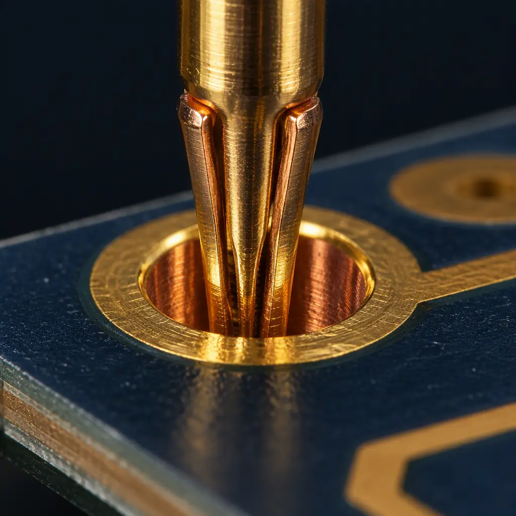
A compliant pin works by elastic and plastic deformation. The pin has a shaped section - the eye of the needle - with a hole through it that lets the two legs flex inward during insertion. On the way in, the legs compress; once seated, the stored elastic energy pushes them outward against the barrel wall with a normal force typically between 40 and 120 N per pin depending on size. That force, distributed over the contact area, creates the cold weld.
Hole Diameter Window
The finished hole diameter is the single most important parameter and the one most often specified loosely. A standard 0.6 mm press-fit pin is normally specified against a finished hole of 0.99 to 1.09 mm. Go below the window and insertion force climbs until the pin buckles or the barrel cracks. Go above it and the required normal force never develops, so the joint holds mechanically but is not gas-tight and will oxidise over time. The window is not a suggestion: it is the design intent of the pin. Always quote finished hole size, never drill size, and state the plating thickness separately because the plating consumes part of the tolerance.
Plating Thickness and Type
Press-fit joints want a ductile barrel that can deform locally without fracturing. Copper thickness in the barrel is typically specified at 25 to 50 µm minimum, with a surface finish that does not add a brittle layer. Hard gold over nickel is the standard for high-reliability backplanes because the surface resists fretting corrosion; thin immersion finishes can fail if the barrel wall is too hard or the copper is too thin. A common failure mode is a barrel that passes electrical test when new and becomes intermittent after thermal cycling, because the copper cracked under the pin and the crack only opens once the board has been through a few hundred cycles.
Aspect Ratio and Board Thickness
Press-fit pins are manufactured for a specific board thickness range, commonly 1.6 to 5.0 mm, with pin length matched to the thickness. The plated through-hole aspect ratio should stay at or below 8:1 for reliable plating in a press-fit application, which is tighter than the 10:1 that is often acceptable for ordinary vias. A pin designed for 2.4 mm stock inserted into a 3.2 mm board does not engage the full barrel and will not develop the specified retention force. This is one of the easiest mistakes to make when a design is transferred between two backplane formats.
Rule of thumb for specification review: if your drawing states a drill size and not a finished hole size, and it does not state barrel copper thickness, the specification is incomplete. Those two numbers, plus board thickness, define whether the joint can work at all. Everything else - pin material, insertion force, press tooling - is downstream of them.
Reading the Press-Force Curve
The insertion-force curve is the only in-process evidence that a press-fit joint formed correctly, and it is worth understanding even if you never touch a press. As the pin enters the barrel the force rises, peaks as the widest part of the eye passes the barrel mouth, then settles to a plateau as the pin seats. Three signature shapes indicate trouble.
| Curve shape | What it means | Action |
|---|---|---|
| Peak far above expected | Hole undersized, or pin oversized, or barrel plating too thick | Stop the run; measure finished hole diameter on actual boards, not the fabrication drawing |
| Flat, low plateau | Hole oversized; pin is not developing normal force | Reject; the joint will not be gas-tight regardless of continuity test results |
| Drop or step mid-insertion | Pin buckling, barrel damage, or off-axis insertion | Inspect pin and barrel under magnification; check press tooling alignment |
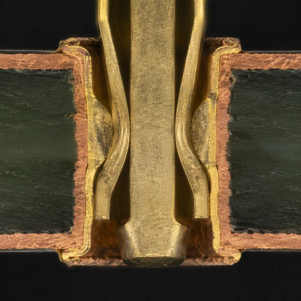
Continuity test alone is a weak acceptance criterion because a marginal press-fit joint is electrically continuous when new. If the programme is high-reliability, require press-force monitoring with per-pin limits, and require a sample cross-section to confirm the cold weld has actually formed rather than a bright metal contact that will oxide.
Press-Fit and Reflow on the Same Board
Most modern backplanes carry both press-fit connectors and surface-mount devices, which forces a process decision: press after reflow, or press before. The industry standard is press after reflow, and the reasons are thermal and mechanical rather than conventional.
Pressing after reflow means the connectors are never exposed to the 245 to 260 °C peak the SMT process requires. Connector bodies are moulded thermoplastics that can creep or warp at reflow temperature, and a warped housing changes the pin-to-hole alignment across the whole array. Pressing after reflow also lets you discard boards that fail SMT inspection before you install expensive press-fit hardware, which improves yield economics on a high-value assembly.
Pressing before reflow is chosen when the connector cannot survive a separate press operation later, or when the assembly sequence demands it. In that case the connector must be rated for the full reflow profile, and the housing material has to hold its dimensional stability through the excursion. Verify with the connector vendor that the specific part number is rated for the specific peak temperature and time-at-temperature, not just that the family is described as reflow-compatible.
Design Rules That Prevent Field Failures
Several layout decisions shift a press-fit design from workable to robust, and they cost nothing if made early.
| Design rule | Target | Reason |
|---|---|---|
| Anti-pad clearance around press-fit barrels | ≥0.25 mm to adjacent copper | Prevents barrel-to-plane shorting when the barrel deforms outward during insertion |
| Keepout around connector footprint | Height of tall components ≥5 mm clear | Press tooling needs direct vertical access to every pin row |
| Board support during press | Full backside support under the connector area | Unsupported boards flex and crack barrels in the middle of an array |
| Pin-in-hole pattern tolerance | Datum the connector to two tooling holes, not to board edges | Edge-to-pin cumulative tolerance is too large across a 400 mm array |
| Thermal relief for press-fit grounds | Direct connection or controlled relief per current | Press-fit ground pins carry high current; relief geometry affects both |
The tooling-hole datum point deserves emphasis. On a long backplane the board outline itself can vary by more than a millimetre, and if the connector pattern is dimensioned from the outline the cumulative error across a wide array exceeds the hole tolerance window. Datum the press-fit pattern to the same tooling holes the press fixture uses, and the pin-to-hole alignment stays inside tolerance regardless of how the outline was routed.

Inspection and Documentation Package
Because a good press-fit joint is invisible from the surface, the acceptance evidence is carried by documentation rather than visual inspection. A complete package for a high-reliability press-fit programme includes: finished hole diameter measured on a sample of actual production boards with the measurement method stated; barrel copper thickness from a cross-section; press-force data with per-pin limits and the number of pins monitored; a cross-section photomicrograph of at least one seated pin showing the deformation zone; and a thermal cycling result on the assembled connector if the product sees wide temperature excursions.
Ask for the cross-section specifically. It is the one piece of evidence that distinguishes a gas-tight cold weld from a joint that merely passed continuity, and it is cheap to produce compared with the cost of discovering the difference in the field.
Frequently Asked Questions
Can press-fit connectors be reworked?
Individual pins can be replaced with dedicated extraction and re-insertion tooling, but the barrel tolerance is consumed by each cycle. Standard practice is to allow a limited number of re-insertions, commonly one to three, and to require a new connector rather than reusing one that has been pressed twice. Boards that have had a connector extracted should be re-measured at the hole before a new pin goes in.
Is press-fit more expensive than soldering?
The connector and the press tooling cost more, and the process is slower per pin than a wave-solder pass. The economics change on pin count and on rework cost: above roughly 1,000 pins per board, the eliminated solder defects and eliminated thermal exposure usually outweigh the tooling cost. Below a few hundred pins, soldered connectors are normally cheaper.
Do press-fit joints need conformal coating?
Not for the joint itself, which is gas-tight by design. Coating is still applied for the surrounding circuitry when the environment requires it, and masking is normally required to keep coating out of the connector mating interface. If coating does migrate into a press-fit barrel before insertion, insertion force rises and the joint quality becomes unpredictable.
What causes a press-fit joint to fail years later?
The two dominant mechanisms are fretting corrosion from vibration with no gas-tight seal, and barrel copper cracking from an undersized hole or insufficient board support at press. Both are traceable to the specification and process controls described above rather than to the connector itself.
