
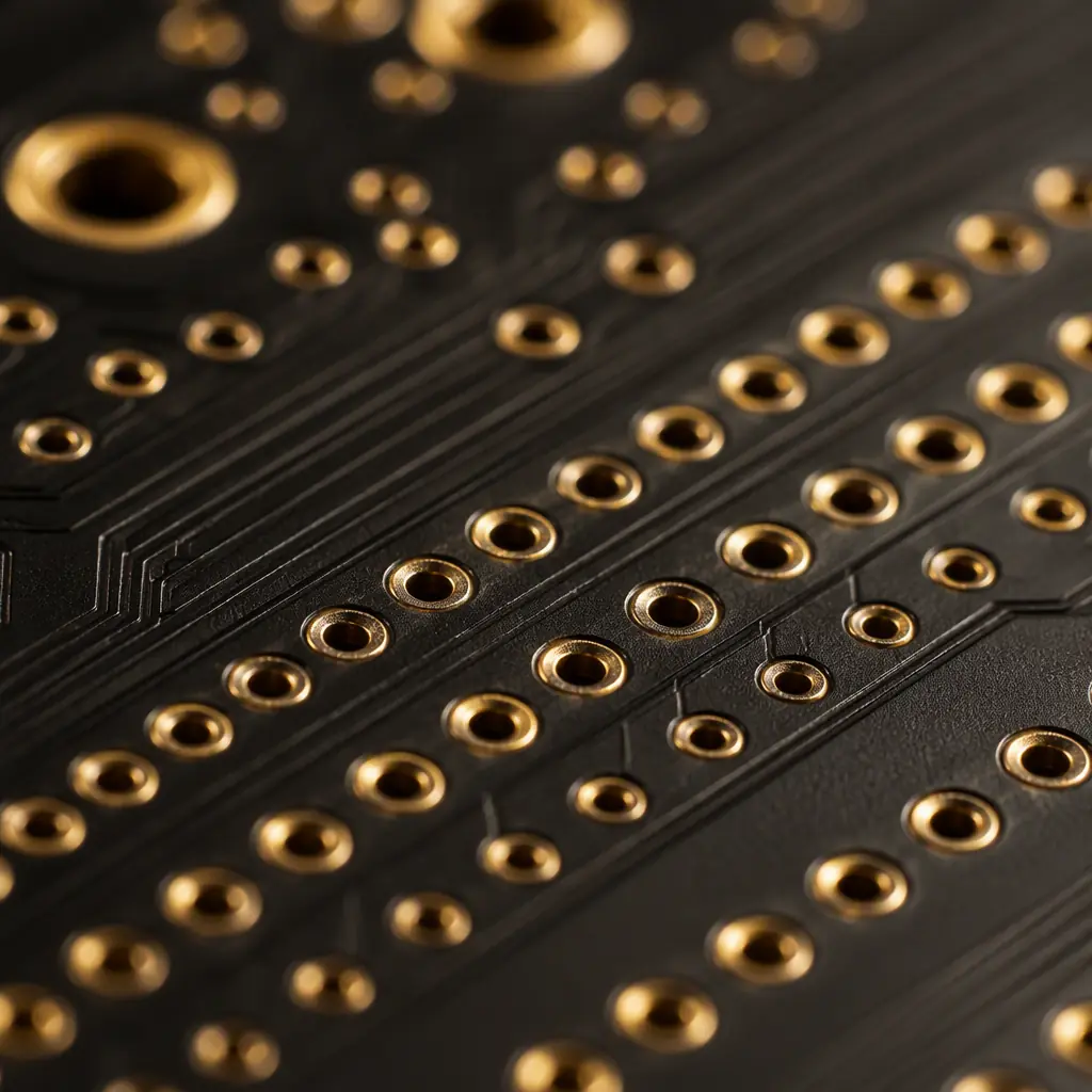
Hole accuracy is the most misunderstood tolerance on a PCB fabrication drawing. A typical drawing says "drill size 0.30 mm" and everyone assumes the finished hole will be exactly 0.30 mm. In reality, the drilled hole, the finished hole after plating, and the position of that hole relative to its pad are three different numbers. And each one is governed by a different tolerance and a different verification method.
When hole accuracy fails, the failures are expensive: press-fit pins that won't insert, annular ring violations that scrap panels at AOI, and via-in-pad misregistration that shows up only in the field. Huaxing PCBA runs 14 CNC drilling machines across two shifts, producing over 80,000 square meters of boards per month, and this guide explains the tolerance system from the drawing side so you can spec it correctly the first time.

Drilled Size vs Finished Size: The Two Numbers on Every Drawing
Every plated hole has a drilled size and a finished size. The drilled size is what the CNC spindle cuts through the copper-clad laminate. The finished size is what remains after electroless copper and electrolytic plating: typically 0.075–0.10 mm smaller than drilled because plating deposits copper on the barrel wall.
| Parameter | Standard (IPC-6012 Class 2) | Tight (Class 3) | Verification |
|---|---|---|---|
| Drilled hole size tolerance | ±0.076 mm (0.003") | ±0.05 mm (0.002") | Hole gauge / pin gauge |
| Finished hole size tolerance | ±0.075 mm | ±0.05 mm | Cross-section measurement |
| Hole position tolerance (true position) | ±0.075 mm | ±0.05 mm | First article / vision inspection |
| Min annular ring (external layer) | 0.05 mm (0.002") | 0.075 mm (0.003") | Microsection + vision |
The confusion between drilled and finished size causes real quoting errors. If your drawing specifies finished hole size, the factory must add plating allowance when selecting the drill bit. A 0.30 mm finished hole needs a 0.375–0.40 mm drill. Our Gerber file guide explains how drill data is encoded so this ambiguity disappears at the quoting stage.
Key Takeaway: State whether your drill chart lists drilled or finished size. IPC-6012 quotes apply to finished holes, but the drill chart convention varies by factory. One explicit note, "All holes finished size unless marked DRILL", eliminates the most common source of hole-size disputes.
Hole Position Accuracy: True Position, Not Just Size
Hole position accuracy is the deviation between where the drill actually lands and where the design data says it should be. It is a function of the drilling machine's positioning system, the drill bit's runout and wander, the panel's dimensional stability through lamination, and the registration system that aligns the drill to the inner layers.
For a standard through-hole board, position tolerance of ±0.075 mm (true position) is achievable with any well-maintained CNC driller. For HDI boards drilling blind and buried vias against inner-layer targets, position accuracy becomes the dominant yield factor. The drill must hit a copper pad on an inner layer that may have shifted during lamination. This is why HDI designs demand tighter registration tooling and why the tolerance class on the drawing directly affects cost.

What drives position error
Machine positioning and calibration
Modern CNC drillers hold ±0.02–0.03 mm positioning repeatability, but calibration drift, spindle wear and temperature changes accumulate error. Production machines are verified daily with test panels; ask your CM how often they calibrate and whether they publish drift logs.
Bit runout and wander
Every drill bit flexes slightly during entry. Small-diameter bits (0.20–0.30 mm) are more prone to wander than 1.0 mm bits. This is why microvia position accuracy is inherently harder than through-hole accuracy, the mechanics work against you at small diameters.
Panel dimensional stability
Lamination shrinks and expands the panel anisotropically, more along the weave direction than across it. High-Tg and PTFE materials move more than standard FR-4. The drilling department compensates using measured expansion factors, but residual error remains. Our materials guide covers which substrates move most.
Layer registration vs hole position
Hole position is measured relative to the panel datum; layer registration is how well inner layers align to each other. The combination determines annular ring. A hole can be perfectly positioned yet have zero annular ring if the inner layer underneath shifted. Our tolerances guide breaks down registration in detail.
Annular Ring: The Tolerance That Combines Everything
Annular ring is the copper remaining around a hole after drilling, the distance from the hole edge to the pad edge. It is the single most inspected dimension on a PCB because it directly controls electrical connectivity and is easy to measure in cross-section. IPC-6012 requires minimum annular ring of 0.05 mm (Class 2) on external layers, with Class 3 designs typically held to 0.075 mm or better.
Annular ring failure has three causes: hole position error, pad size too small for the tolerance budget, and inner-layer registration shift. The design rule that prevents it is the annular ring budget: pad radius minus (hole radius + position tolerance + registration tolerance) must stay positive. When a CM asks you to enlarge a pad or tighten a tolerance, they are protecting this budget.
Procurement Tip: When a quote comes back with a "tight drilling tolerance" surcharge, ask what the annular ring budget is. A well-designed board with adequate pads holds Class 3 annular ring at standard drilling cost. The surcharge is often for an over-constrained drawing, not for real capability.
Press-Fit and Backdrill: Where Hole Accuracy Becomes Functional
For most connections, a slightly off-position hole still works electrically. Press-fit and backdrilled holes are different: hole geometry is the function.
Press-fit holes
Press-fit (compliant pin) connectors rely on interference between the pin and the plated hole wall. IPC-6012 and connector manufacturers specify finished hole tolerances of ±0.05 mm or tighter for press-fit zones, and hole position accuracy must hold across the entire connector footprint. A multi-pin connector can have 100+ holes, and each one must align with its pin simultaneously. Our press-fit technology guide covers the full specification chain from drawing to insertion.
Backdrilled holes
Backdrilling removes the unused stub of a via barrel to improve signal integrity above 5 Gbps. The backdrill operation drills a larger hole from the back side to a controlled depth. And depth control plus concentricity with the original via determine whether the stub is fully removed. A misaligned backdrill can nick the barrel plating and turn a signal-integrity fix into a reliability defect. Our backdrilling guide details the depth and tolerance requirements.
How to Verify Hole Accuracy, First Article, Microsection, and In-Process Checks
Hole accuracy is verified at three levels, and a good CM does all three. Knowing what to ask for turns a passive purchase into an audited one.
First-article dimensional report
On the first article, the factory measures hole sizes with pin gauges and position with a vision/CMM system. Ask for this report, it shows the actual distribution, not just pass/fail. Deviations clustered at the tolerance edge indicate a process that needs adjustment before production.
Microsection analysis
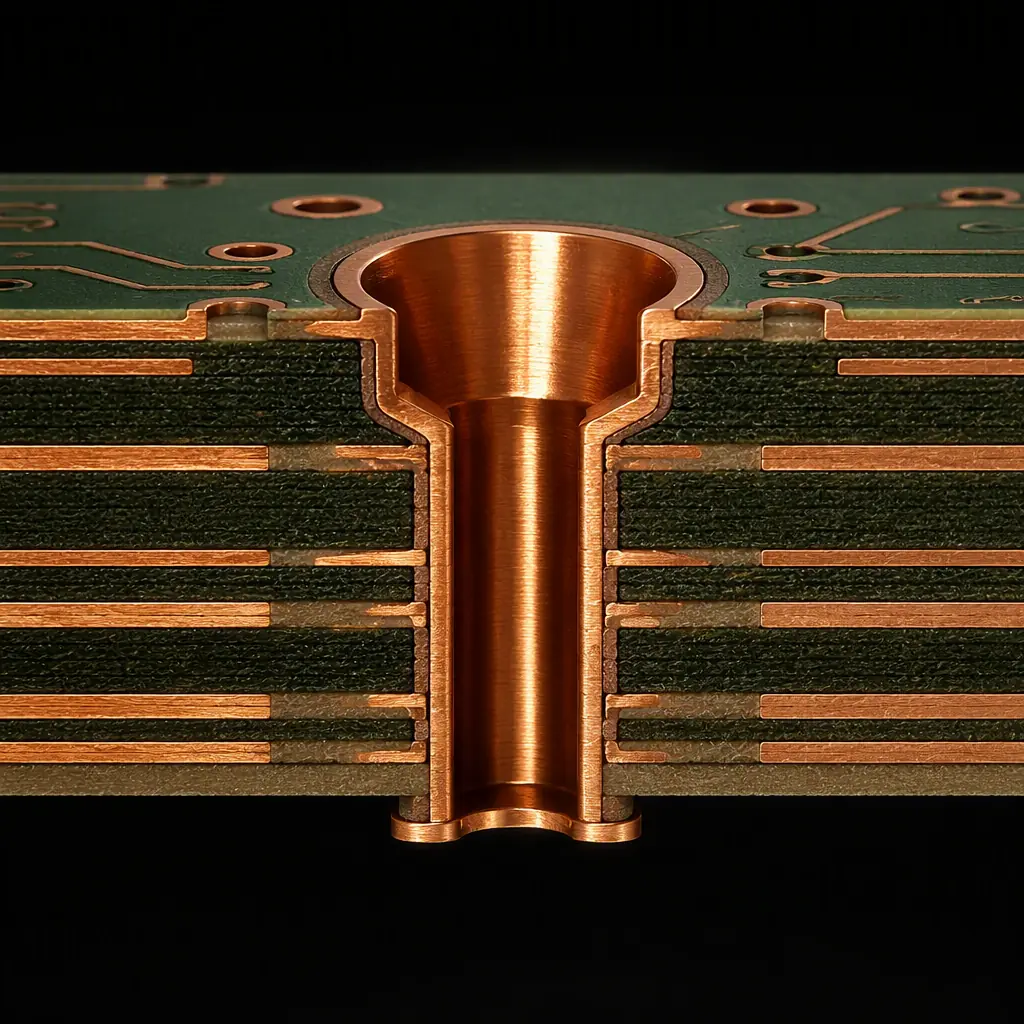
Cross-sectioning reveals finished hole size, barrel plating thickness, and annular ring on the internal layers, the dimensions no vision system can see. Standard practice is 2–3 coupons per panel. Our microsection guide explains how to read the report and what the measured values mean.
In-process drilling verification
Production drillers run automatic bit-breakage detection and periodic test coupons. Ask whether the factory uses auto-tool-length measurement and how frequently it verifies the drill pattern against the CAM data. This is the difference between catching drift at 100 panels and catching it at 10,000.
Specifying Hole Accuracy on Your Drawing, A Practical Checklist
State drilled vs finished size explicitly
Add one note: "Hole sizes are finished size unless marked DRILL." This removes the single biggest source of hole disputes.
Specify IPC-6012 class for holes
Class 2 for general products, Class 3 for automotive, medical, aerospace and high-reliability industrial. The class drives annular ring, plating and inspection requirements. Our IPC Class 2 vs 3 comparison helps you choose.
Flag press-fit and backdrill zones
These get tighter tolerances and dedicated verification. Put them in the drill table with a note, not just in general specifications, so the quoting and CAM teams see them.
Request first-article hole report
One line on the purchase order: "First article to include hole size and position report." It costs the factory 30 minutes and gives you the data to approve or correct before production runs.
Verify annular ring on internal layers
External annular ring is visible; internal annular ring is not. If your board has tight-pitch inner layers, ask for microsection measurement of internal annular ring on the first article, this is where registration problems hide.
Summary: Hole Accuracy Is a System, Not a Number
Drilled size, finished size, position, and annular ring form one tolerance system. Spec it consciously: state the size convention, choose the IPC-6012 class, flag functional holes, and verify with first-article reports and microsection. Boards that pass this discipline ship with predictable quality, boards that skip it fail in unpredictable places.
At Huaxing PCBA, our drilling department holds ±0.05 mm position accuracy on standard through-hole production and supports laser-drilled microvias down to 0.075 mm for HDI builds. Every production order ships with microsection verification on request, and first-article hole reports are standard on new designs. Read our drilling technology comparison for the process-level view, or send your drill chart for a tolerance review with your quote.
