
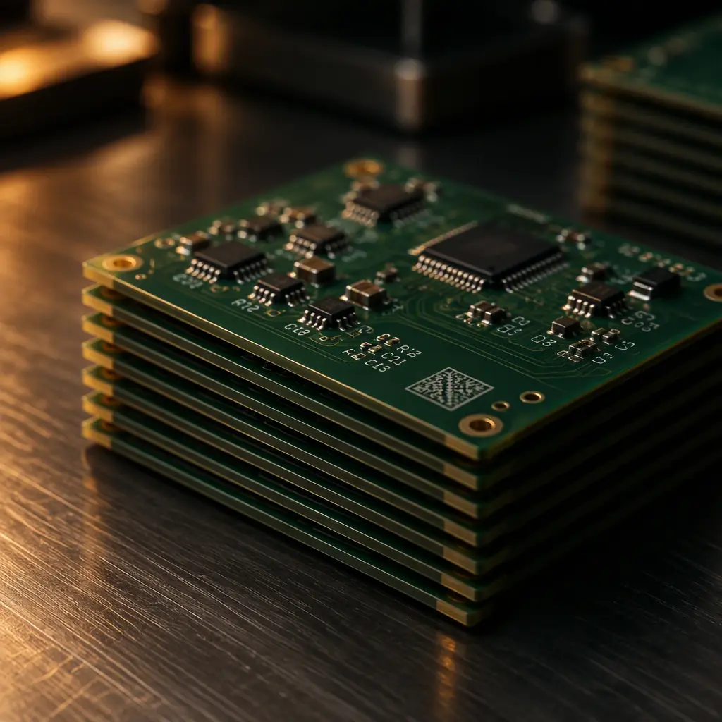
Marking is the part of a build package that receives the least attention during design and causes the most trouble after shipment. A buyer who needs to trace a defect back to a specific production lot, or who has to demonstrate unique identification to a defence prime or a notified body, does not need a supplier who can print a part number. They need a supplier who has thought about which marking technology produces a mark that is still readable after reflow, wave solder, aqueous wash and conformal coating, and that is a different specification entirely.
The practical problem is that most marking decisions are deferred to the fabrication stage, where they default to whatever the silkscreen artwork happens to contain. That is fine for a commercial board with no traceability obligation. It is not fine for a defence build that falls under DFARS unique identification, a medical device that needs a UDI carrier on the device itself, or any product where a warranty claim will hinge on proving which panel a specific serial number came from. This guide covers what marking must appear, how the three main marking technologies compare, how the major traceability regimes map onto the board surface, and how to specify marking so it still works after the board has been through the oven. At Huaxing PCBA we produce 32-layer boards and assemblies with in-line laser marking and serialised traceability, and marking validation is part of the first-article routine rather than an afterthought.

What Marking Must Actually Appear on a PCB
There is no single standard that says "a PCB shall be marked with X." The required set is assembled from product standards, customer flow-downs and regulatory regimes, and it varies enormously between a consumer board and an aerospace assembly. What follows is the realistic minimum, and then the layers that get added on top.
| Marking element | Typical driver | Permanent? |
|---|---|---|
| Manufacturer identification | UL recognition, commercial traceability | Yes, etched or silkscreen |
| Part number and revision level | Customer drawing, configuration control | Yes, etched or silkscreen |
| Date or lot code | Traceability, warranty, recall scoping | Usually, laser, ink or label depending on regime |
| Flammability rating mark (e.g. 94V-0) | UL 94 via the laminate supplier | Yes, part of laminate identification |
| ESD / handling warnings | Internal handling procedure | Optional, often on packaging instead |
| Unique identifier (UID / serial) | DFARS 252.211-7003, UID programmes | Yes, must be permanent and machine-readable |
| UDI carrier | EU MDR 2017/745, FDA 21 CFR 830 | On device or packaging depending on device class |
Two distinctions matter here and they get conflated constantly. The first is between the reference designator legend and identification marking. Designators (R12, C4, U7) exist to support assembly and rework; they are engineering content. Identification marking (part number, revision, lot) exists to support traceability. A board can have excellent silkscreen designators and no traceable identification marking at all, and that board will fail an audit. Our PCB silkscreen legend design guide covers the designator side; this article covers the identification side.
The second distinction is between permanent and non-permanent marking. A mark applied with ink or a label can be removed with solvent or peeled off; a laser mark changes the solder mask itself and cannot be removed without destroying the surface. Where a standard or contract requires a permanent unique identifier, ink and labels are not compliant substitutes regardless of how well they read at first-article.
Ink Marking, Laser Marking and Silkscreen Compared
The three technologies are not ranked; they solve different problems. The table below is the decision view rather than the feature view, because the features are usually the same across suppliers and the costs and constraints are not.
| Attribute | Silkscreen legend | Inkjet marking | Laser marking |
|---|---|---|---|
| Tooling | Screen per artwork, real setup cost | None; data-driven from file | None; data-driven from file |
| Best for | Static content, high volume, whole-panel coverage | Variable data, mixed product output, reworkable codes | Permanent UID, small 2D codes, boards with no legend space |
| Permanence | Printed under or over mask; robust but removable with aggressive solvent | Low, can be washed or erased | High, mask is physically altered |
| Character resolution | Limited by mesh and ink bleed | Good, machine-dependent | Highest, fine characters and dense 2D codes |
| Effect on substrate | None | None to minimal (ink build-up) | Local mask discolouration; depth must be controlled |
| Change cost per new code | New screen or artwork revision | Zero, new data file | Zero, new data file |
| Typical fit | Volume commercial boards | NPI, mixed-model lines, date codes | Defence, medical, serialised product |
The cost logic is straightforward once you separate setup from unit cost. Silkscreen carries a one-time artwork or screen cost but the lowest marginal cost per panel, so it wins decisively at high volume with static content. Inkjet and laser carry no tooling and are driven directly from a data file, so the marginal cost of changing a date code, a lot number or a full serial number is effectively zero. That is why the practical answer for most mixed-product factories is a hybrid: silkscreen for the designator layer, and a data-driven inkjet or laser head for the variable identification content.
The durability difference is what drives the choice on regulated work. Inkjet codes sit on the mask surface and are vulnerable to the same solvents used during cleaning and rework. Laser marking ablates a controlled depth of the solder mask, producing a mark that is part of the board rather than on it. Where the requirement is a permanent unique identifier, laser is the only one of the three that satisfies it. The trade-off is process control: laser parameters must be tuned per mask type and colour, because over-marking exposes the copper underneath and under-marking produces a mark that fades after coating. Both of which are first-article failures rather than gradual drifts.
Design note: Every marking technology needs a defined keep-out area. Laser and inkjet marking heads cannot operate over exposed copper, gold fingers, solderable pads or test points, and marking placed under a component footprint will be hidden after assembly. Marking windows should be defined in the fabrication drawing as an explicit keep-out layer, not left to the fabricator's judgement.

Traceability Marking: UID, Data Matrix and 2D Codes
When a contract or regulation requires machine-readable identification, three questions determine the specification: what construct must the code contain, what symbology carries it, and what print quality grade is acceptable. Getting the first right and the third wrong is the most common failure, because a code that exists but reads poorly is not traceability, it is an audit finding waiting to happen.
| Regime | Applies to | Carrier | What it must encode |
|---|---|---|---|
| DFARS 252.211-7003 / UID | Defence items above the specified threshold | Permanent 2D Data Matrix | Enterprise identifier plus a unique serial within it |
| AS5553 (counterfeit avoidance) | Aerospace and defence supply chains | Board and package marking | Authentic, traceable manufacturer identification through the chain |
| EU MDR 2017/745 Article 27 | Medical devices placed on the EU market | UDI carrier on device or packaging | Device identifier plus production identifiers (lot, serial, expiry) |
| FDA 21 CFR 830 | US medical devices | UDI carrier | Device identifier plus production identifiers |
| GS1 General Specifications | Commercial supply chains, retail-adjacent | GS1 DataMatrix or QR | GTIN plus application identifiers (batch, serial, date) |
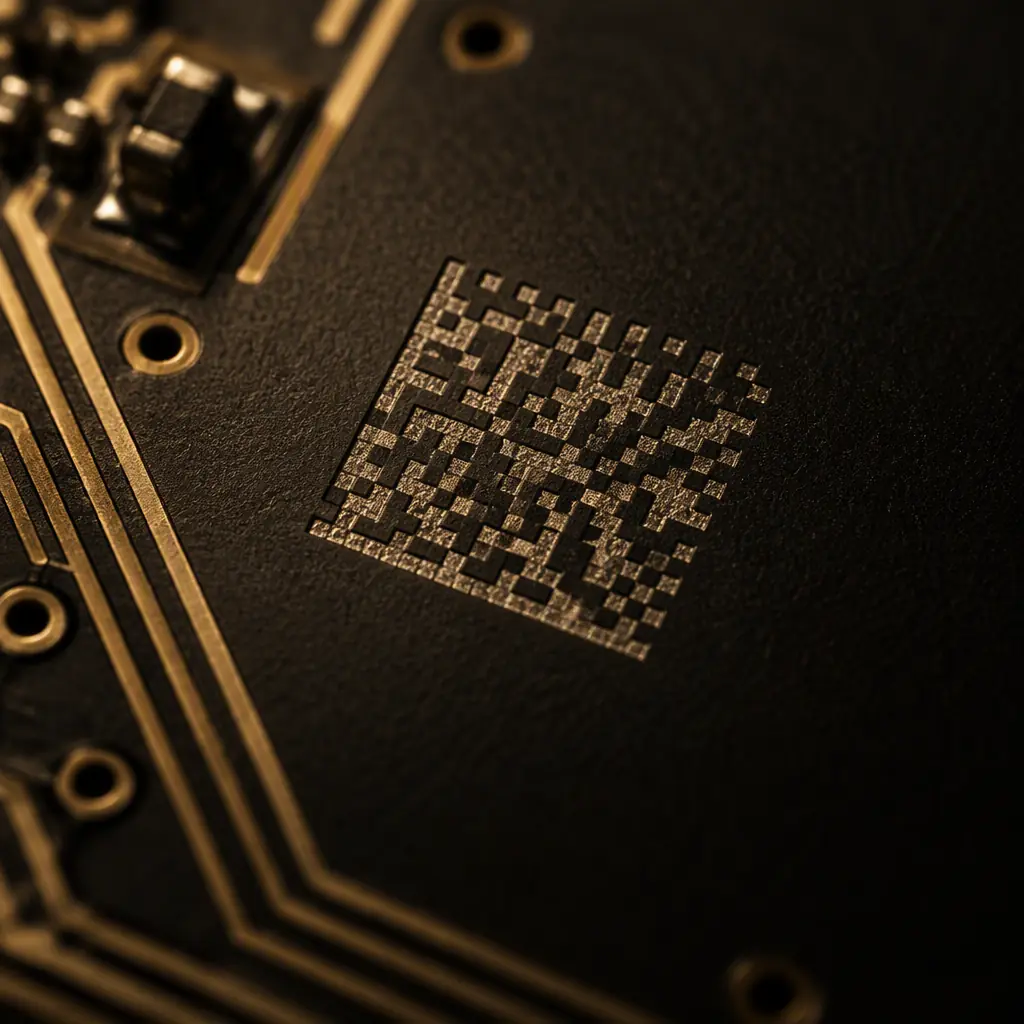
The mechanism behind all of these is the same: a data structure wrapped around an identifier, carried in a 2D symbol, with a required print-quality grade. For a Data Matrix, the relevant quality standard is ISO/IEC 15415, which grades a symbol on a letter scale across parameters including symbol contrast, modulation, fixed pattern damage and axial non-uniformity. A grade of C or better (some programmes specify B or A) is the usual acceptance threshold, and it must be measured after the board has been through assembly, not on a bare marked panel before reflow and coating.
This is where a marking specification most often comes apart. A laser-marked Data Matrix on bare laminate can grade A and still fall to D after conformal coating, because the coating changes the surface reflectance and fills the individual cell geometry. If your acceptance test is run at the fabrication stage only, you will certify a code that no longer reads when the finished assembly arrives at your customer. The specification must state the measurement stage explicitly.
Marking for Medical and Regulated Products
Medical device marking adds a layer that commercial boards never encounter: the identifier must be tied to a regulatory database entry, and the linkage has to survive for the life of the device record. The practical implications for a PCB supplier are narrower than they first appear but they are absolute.
Establish whether the UDI carrier is on the device or the packaging
Device class drives this. For many Class I and some Class II devices the UDI can be carried on the label or packaging rather than the device itself, which means the bare board may need no UDI marking at all. Large or reusable devices almost always require the carrier on the device. Confirm this before specifying laser marking, because retrofitting a 2D code into a tight board layout after design freeze is expensive.
Confirm the lot or serial linkage the device record requires
A UDI production identifier is only useful if it resolves to a manufacturing record. That means the marking on the board has to link to your supplier's process data, which panel, which lot, which date, which test result. Ask for the field structure rather than the format, because a serial number that cannot be joined back to a test log is not a traceability system.
Validate legibility after sterilisation where applicable
Devices that are sterilised can see marking degrade through the sterilisation cycle, particularly inkjet codes exposed to high humidity or oxidising agents. If the device is sterilised, the marking validation must include a post-sterilisation read, not just a post-assembly read.
The common thread across medical, defence and aerospace is that marking is a validated characteristic rather than a cosmetic one. It needs a defined acceptance criterion, a defined measurement method and a defined measurement stage. That is a documentation question as much as a process question, and it is worth reading alongside our guide to the PCB test report and documentation package to see how marking records fit into the wider evidence set.
Labels That Survive Assembly
Adhesive labels are the cheapest way to add variable identification and by far the most common source of traceability failure, for a simple reason: they are usually applied at a stage where nobody has considered what the board is about to go through. A label that reads perfectly at the inspection bench can be curled, discoloured or gone by the time the assembly ships.
Match the label's temperature rating to the peak reflow profile
A lead-free reflow profile peaks in the range of 245–260 °C for a short dwell. Many general-purpose label stocks are rated for continuous operating temperature, not for a transient peak, and the two numbers are not interchangeable. If the label goes on before reflow, the specification must be a reflow-rated stock with a documented peak-temperature capability and an adhesive that does not outgas.
Keep labels out of wash and coating zones
Aqueous cleaning and conformal coating are both hostile to adhesive. Coating applied over a label can lift the edge, and wash chemistry can wick under the adhesive and carry contamination onto the board. Where a label is unavoidable on a coated assembly, it belongs in a masked area with the mask called out on the drawing.
Decide whether marking goes under or over the coating
Marking that will be read in service should generally go under the coating, because the coating protects it and the reading is done through a known optical layer. Marking applied over the coating is exposed to handling and chemicals but easier to re-mark. Either choice is defensible; the failure mode is leaving it undecided so that the same part number comes back marked differently on different lots.

The interaction with surface protection is worth planning deliberately rather than leaving to process default. Our comparison of PCB coating types covers the optical and thickness differences that affect whether marking placed underneath remains legible, and the conformal coating process guide covers the application stages where a label or a mark can be compromised.
Legibility and Acceptance Criteria
Marking is inspectable, which means it can and should have numeric acceptance criteria rather than a subjective "readable" instruction. The following are the parameters to specify, and they apply to first-article inspection and to ongoing production alike.
| Parameter | Practical specification | Why it matters |
|---|---|---|
| Character height | Minimum height defined by the fabricator's legend capability; state it on the drawing | Below the practical limit the legend closes up during printing or is unreadable under magnification |
| Contrast | Sufficient optical contrast between mark and mask for automated reading | Low contrast passes human inspection and fails camera reading |
| 2D code grade | ISO/IEC 15415 grade C or better, measured at the stated stage | Grade drift after coating is invisible without staged measurement |
| Legibility after rework | Re-marked or replaced where the mark is obscured by rework | A legible partial code that omits a character reads as a valid different code, the worst outcome for traceability |
| Mark-to-edge distance | Defined keep-out from board edge, v-score and route paths | Marking lost during depanelling destroys identification on the finished board |
The rework case deserves emphasis. When a component is replaced near a laser-marked serial, the mark is often partially obscured but still reads to a decoder as a legitimate string. That produces a board carrying a serial number belonging to a different unit, which is a genuine traceability hazard and considerably worse than an unreadable mark. The specification should require that any marking affected by rework is re-marked, and that re-marked units are recorded, rather than relying on the operator to judge readability.
Specifying Marking in Your Build Package
Marking that is not specified gets defaulted, and defaults vary between fabricators and between lots. The following checklist covers what needs to be defined before the first order, and each item maps to a specific failure it prevents.
State which content is artwork and which is machine-applied
Designators, part number and revision are normally part of the silkscreen artwork. Date code, lot and serial are normally machine-applied variable data. Making the split explicit stops a supplier from printing a fixed date code into the artwork, which is a surprisingly common error.
Define the variable-data source and its format
If serials are supplied by the buyer, provide the file format, the per-panel or per-board granularity, and the sequence rules. If the supplier generates serials, require the range to be reported back with the shipment so your records and theirs agree.
Call out the marking keep-out layer
Marking zones must exclude gold fingers, solderable pads, test points, component footprints, v-score lines and route paths. Put them on a dedicated layer in the fabrication data rather than describing them in a note.
Specify the permanence class required
Use the language of the governing regime: a permanent unique identifier where DFARS or a durability requirement applies, and variable identification marking where it does not. This single sentence decides laser versus inkjet and prevents a non-compliant substitution.
State the measurement stage and acceptance grade
For any 2D code, write down whether the grade is measured on bare board, after assembly, or after coating, and what grade is required. This is the specification line that most often goes missing and the one that causes disputes at goods-in.
Require marking records in the shipment documentation
Ask for the serial or lot range applied, the marking method used and the inspection result. Without this the marking exists on the board but cannot be joined to any record, which defeats the purpose of applying it.
Frequently Asked Questions
What marking is mandatory on a PCB? There is no universal mandatory set. In practice a board should carry manufacturer identification, part number and revision, and a date or lot code for traceability, with a flammability rating where UL recognition applies. Defence, medical and aerospace programmes add mandatory unique identification or UDI carriers under DFARS, AS5553, EU MDR or FDA rules. The governing contract or regulation determines the requirement, not a single PCB standard.
Can an inkjet code be used for a permanent unique identifier? No. Ink sits on the solder mask surface and can be removed with solvent or abraded, so it does not meet permanence requirements for UID or UDI on the device. Those programmes require a permanently affixed or embedded mark, which in practice means laser marking or a validated permanent label.
Does conformal coating affect 2D code readability? Yes, and often enough to drop the grade below the acceptance threshold. Coating changes surface reflectance and fills the cell geometry of a Data Matrix. The code must be graded after coating if the finished assembly is where it will be read, which is why the measurement stage belongs in the specification.
Marking as a Validated Characteristic, Not a Detail
Every traceability regime comes down to the same requirement: the identification on the board must resolve to a manufacturing record, and that resolution has to still work after the board has been through the entire assembly process. Achieving that means choosing marking technology by permanence requirement rather than by habit, defining keep-outs before layout freeze, specifying where the code grade is measured, and requiring the applied serial or lot range to come back with the shipment.
At Huaxing PCBA we mark with in-line laser marking and inkjet across a 15,000 m² facility with 8 high-speed SMT lines, delivering serialised and lot-traced boards to 150+ active customers in 30+ countries. Marking is validated at first article and verified through production under ISO 9001 and IATF 16949 certification, with IPC-A-610 Class 2 and 3 acceptance criteria applied to legibility. Boards are fabricated to 32 layers with a minimum trace and space of 3 mil, and marking keep-outs are checked during DFM review before tooling is released. Send your build package for a quote and DFM review, or talk to our engineering team about a traceability specification.
