
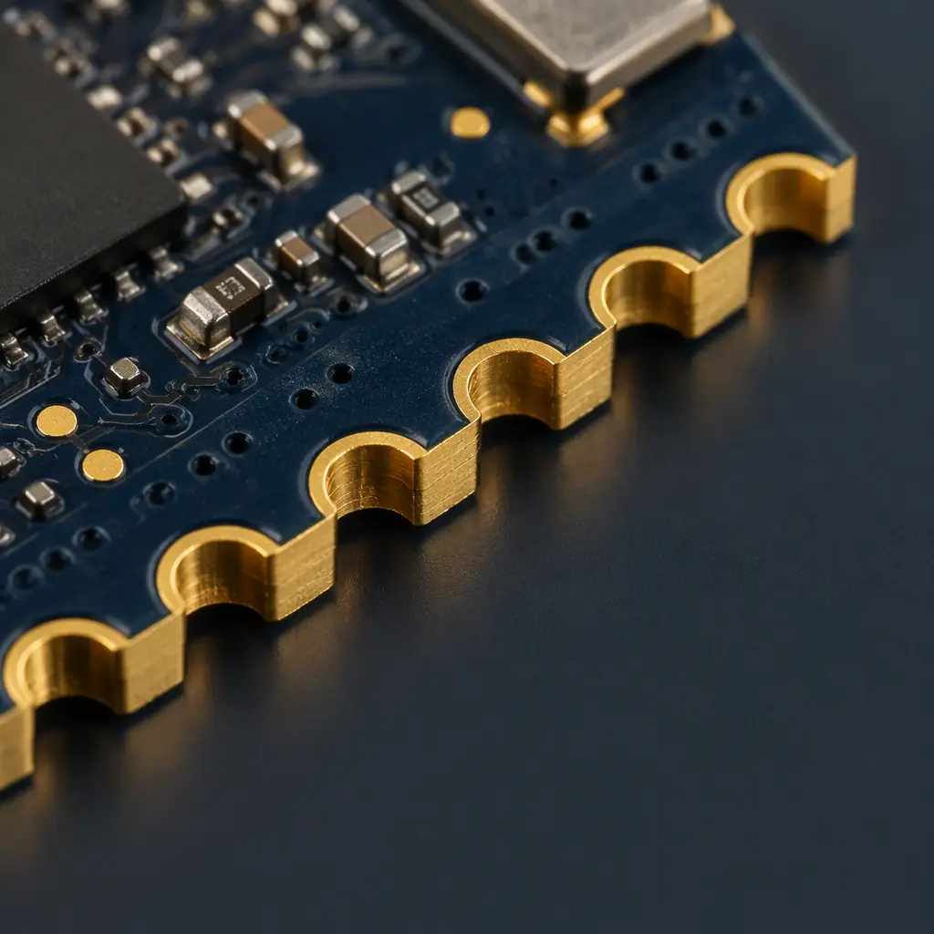
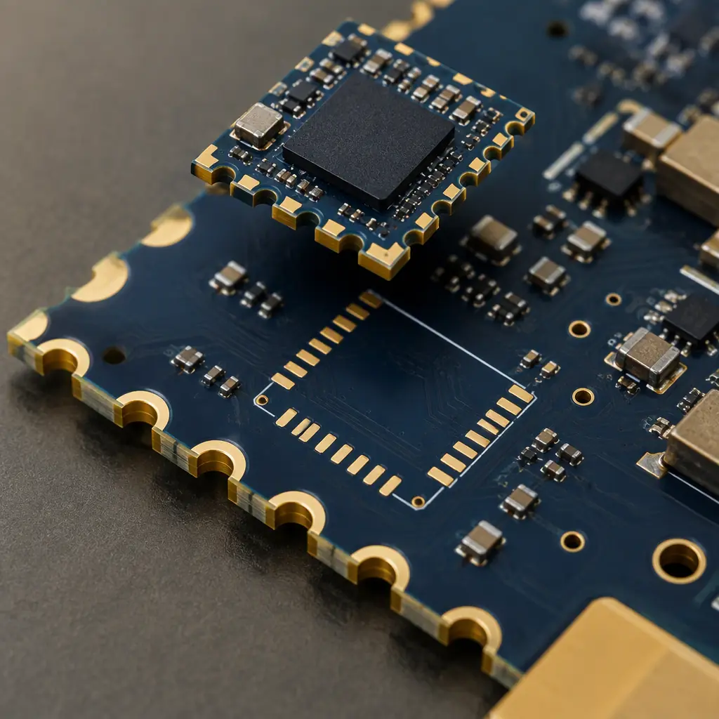
Castellated holes are the mechanical and electrical interface that lets a small module be soldered onto a larger carrier board as if it were a component. The holes sit on the module edge, half of the barrel is removed with the routing, and what remains is a plated half-cylinder that can be reflowed onto a matching footprint. It is the standard attachment for RF modules, DC-DC converters, sensor packages and IoT radio boards. It is also an interface where the PCB fabrication tolerance is the whole specification, and where a few tens of microns of half-hole diameter decides whether the module sits flat at reflow or rocks on a high joint.
This guide covers castellated hole geometry, the fabrication tolerances that actually matter, the stencil and paste decisions that follow from it, and the edge plating variant used where a castellated joint is not mechanically sufficient.
How Castellated Holes Are Made
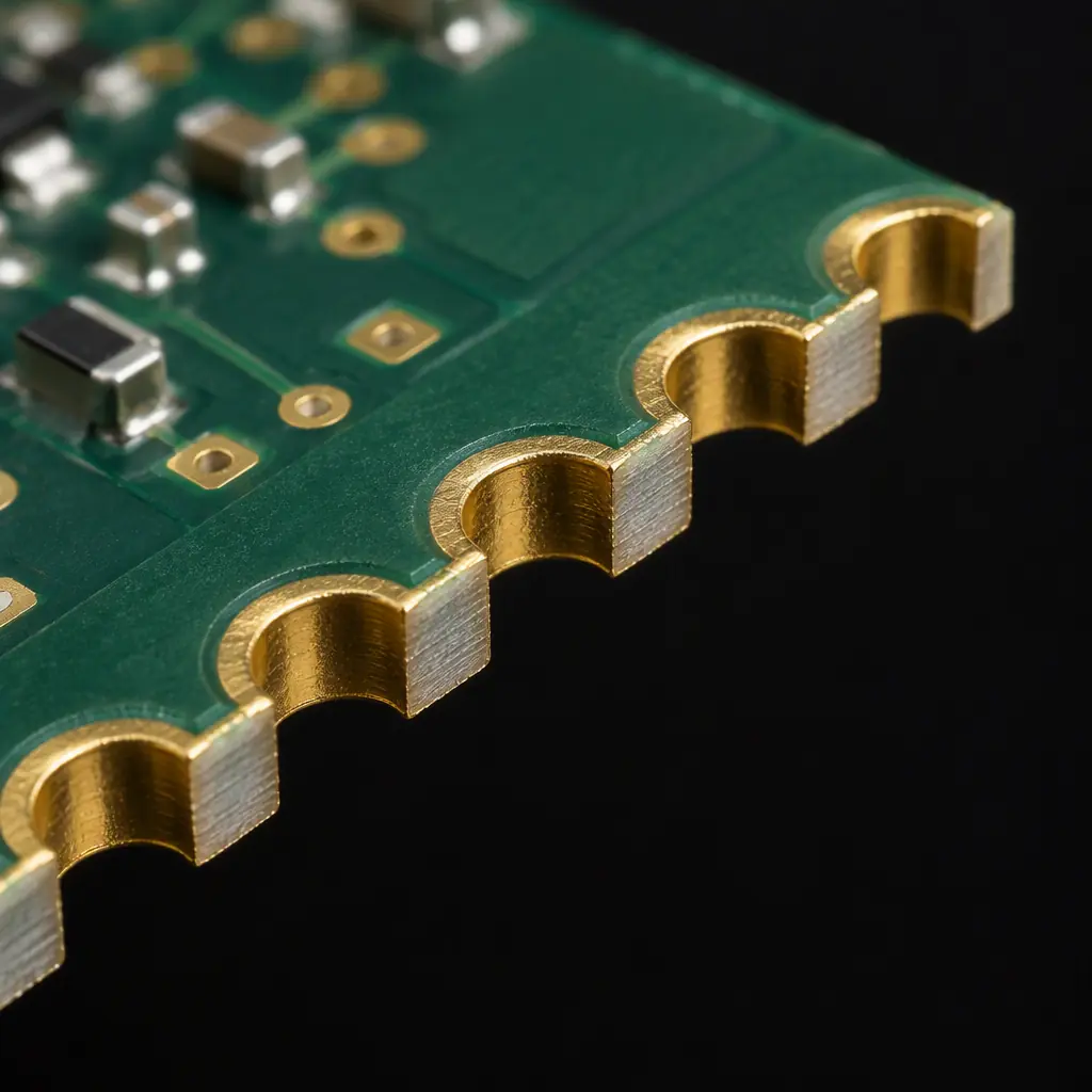
A castellated hole starts life as a normal plated through-hole placed on the edge of the module outline, or on a panel edge that will later be singulated. The hole is drilled and plated with the rest of the board, so the barrel is a continuous plated cylinder. After plating, the module outline is routed straight through the centre of the hole, cutting away half the cylinder and leaving a plated half-moon on the module edge and a mirror half on the scrap.
Two consequences follow directly from that sequence. First, the finished castellated diameter is a function of drill size plus plating thickness, and the routing cut is positioned to the board outline with its own tolerance. Second, the exposed half-barrel has a cut edge where the copper was severed, and that edge is a site for burrs, copper smearing and, on some laminates, exposed fibre. How the fabricator handles that cut edge is a large part of whether the module reflows reliably.
Vias vs Castellated Holes: Different Rules
A castellation is not a via cut in half, and should not be documented as one. The important difference is that the cut exposes the barrel cross-section, so the copper-to-laminate interface is open to the atmosphere and to moisture. This is why castellations on high-reliability products are usually specified with a surface finish that covers the cut copper - hard gold or ENIG over the full half-barrel - rather than relying on the internal plating alone. Specify castellations on a dedicated layer or as a defined hole class in the fabrication drawing so the fabricator does not treat them as ordinary routing.
Half-Hole Diameter Tolerance
The controlling dimension is the finished half-hole diameter measured across the remaining barrel, typically specified between 0.60 and 1.00 mm for standard modules, with a tolerance in the region of ±0.05 mm on good processes and ±0.075 mm on general commercial work. The cut position relative to the module edge is a separate tolerance and is what determines whether the module sits flat: if the cut is offset, the remaining half-cylinder is asymmetric and the module will not register against a symmetrical footprint. State both the half-hole diameter and the cut position, and state which edge is the datum.
Plating Thickness Through the Half-Barrel
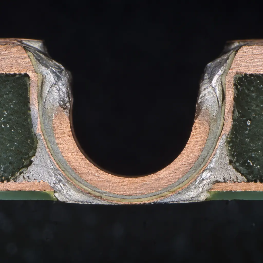
Castellated barrels should be plated to at least the same copper thickness as ordinary vias, commonly 20 to 25 µm minimum, and preferably higher because the barrel carries mechanical load during reflow and handling. The plating must remain continuous through the cut; a barrel that plates well but shows a visible gap or a thin lip at the cut line cannot carry current reliably and will not wick solder evenly. This is one of the few castellated defects that a careful visual inspection under magnification will catch, and it is worth requiring on the first-article inspection.
Specification checklist for a castellated module: finished half-hole diameter with tolerance; cut position tolerance with datum edge; barrel copper thickness; surface finish covering the cut face; maximum burr height at the cut; and the sample size and method for the first-article verification. Six numbers, all cheap to define at design time and expensive to discover at assembly.
Stencil, Paste and Reflow for Castellated Joints
Because a castellated joint is a half-cylinder, it does not behave like a surface-mount pad. Paste volume and stencil design have to be considered together with the module mass.
| Parameter | Recommendation | Reason |
|---|---|---|
| Paste volume on the carrier footprint | Overprint the footprint by 15 - 25% in volume | The half-cylinder needs a fillet on both faces; flat pads need less than castellations do |
| Stencil aperture | Align aperture to the carrier pad, not the module castellation | The module is placed after printing; registration is to the carrier |
| Stencil thickness | 0.10 - 0.12 mm with an area ratio ≥0.66 | Keeps paste release clean on the small pads the castellation spacing produces |
| Placement force | Low, with a soft nozzle and slow Z descent | Excess force pushes paste out of the joint before reflow, causing opens |
| Reflow profile | Standard SAC305 profile, but verify module body temperature | The module itself is a heat sink and may be cooler than the carrier at peak |
| Fillet inspection | Inspect all four faces of each joint | A castellation joint can look complete from above and be open underneath |
The overprint recommendation is the one most often missed. On a flat SMT pad, a full-area paste deposit is correct because the joint only needs one fillet. On a castellated joint, solder has to climb the outer face and fill the inner face of the half-cylinder, so a deposit sized for a flat pad consistently produces a starved joint even when placement and profile are perfect.
Castellation vs Edge Plating
Where a castellated joint does not provide enough mechanical strength - larger and heavier modules, boards subject to vibration, or an interface that must carry substantial current - edge plating is the alternative. Edge plating covers a strip along the module edge with plated copper that extends onto the top and bottom surfaces, giving a continuous metal edge rather than a series of discrete half-cylinders.
The trade-off is fabrication complexity. Edge plating requires the edge features to be plated before routing so the plating wraps the eventual cut, and it demands controlled routing to avoid damaging the plated strip. The payoff is a stronger joint with better current capacity and a more forgiving placement tolerance. The full geometry and tolerance set for both approaches is covered in our PCB edge plating and castellations guide, and the related pad geometry appears in the edge connector and gold finger design guide.
The decision rule is straightforward: use castellations for small, light modules with moderate current per pin; use edge plating when the module is large enough that peel and shear forces at the joint matter, or when a single interface carries several amps.
Panelisation and Singulation
Castellated modules are almost always delivered in panels and singulated at the assembly house or by the carrier assembler. Where the castellation is on the module edge, the routing that removes the module is the same operation that forms the half-holes, which means panel design and castellation tolerance are the same problem.
Two panel decisions matter. The first is depanelisation method: routing leaves the cleanest castellation edge, while V-score cannot be used through a castellated edge because it would damage the half-barrels. The second is the panel rail and tab design; tabs must not pass through a castellation position, and the module must be supported during routing so the half-barrels are not smeared. Our PCB depaneling methods guide and the depanelization guide cover the method selection, and PCB manufacturing tolerances sets out what the routing operation can realistically hold.
Inspection and First-Article Verification
Castellated features should be verified on a first article with a defined method rather than a visual pass. A workable check includes: measurement of the finished half-hole diameter on a sample of at least ten castellations across the module, using a method that can resolve the stated tolerance; measurement of cut position relative to the datum edge on the same sample; microsection through at least one castellation to confirm barrel continuity and plating thickness at the cut; a burr-height check under magnification; and a reflow trial of one module onto a carrier with cross-section of the resulting joints.
That reflow trial is worth the effort because it is the only step that tests the interface as the customer will use it. A module can pass every dimensional check and still produce starved joints because the paste deposit was sized for a flat pad, and the cross-section is how you find out before the production run rather than after.
Frequently Asked Questions
Can castellated holes be half-filled or plugged?
They can, but it is unusual and it changes the joint behaviour. A filled castellation no longer presents a half-cylinder for solder to climb, so the joint becomes a surface connection rather than a barrel connection. Specify filled castellations only if the module vendor's assembly process expects them, and confirm the paste volume with them first.
What surface finish should castellated edges use?
ENIG or hard gold over nickel are the common choices because both cover the cut copper face and resist oxidation on the exposed barrel cross-section. Hasl finishes can bridge across a small castellation during the hot-air levelling step, which is a defect that is difficult to rework. OSP leaves the cut copper unprotected and is a poor fit for long-storage modules.
Why do my castellated modules not sit flat?
Usually because the cut position tolerance was not specified separately from the half-hole diameter. A symmetrical footprint expects the remaining half-cylinders to be symmetric about the module edge; if the route is offset, the module registers on one face and rocks. Specify cut position with a tolerance and a datum edge.
How much paste should the carrier footprint get?
Start 15 to 25 per cent above the volume a flat pad of the same area would receive, then verify with a cross-section. The extra volume fills the inner face of the half-cylinder, which a flat-pad calculation does not account for. Overprinting too far causes bridging between adjacent castellations, so verify rather than assume.
