
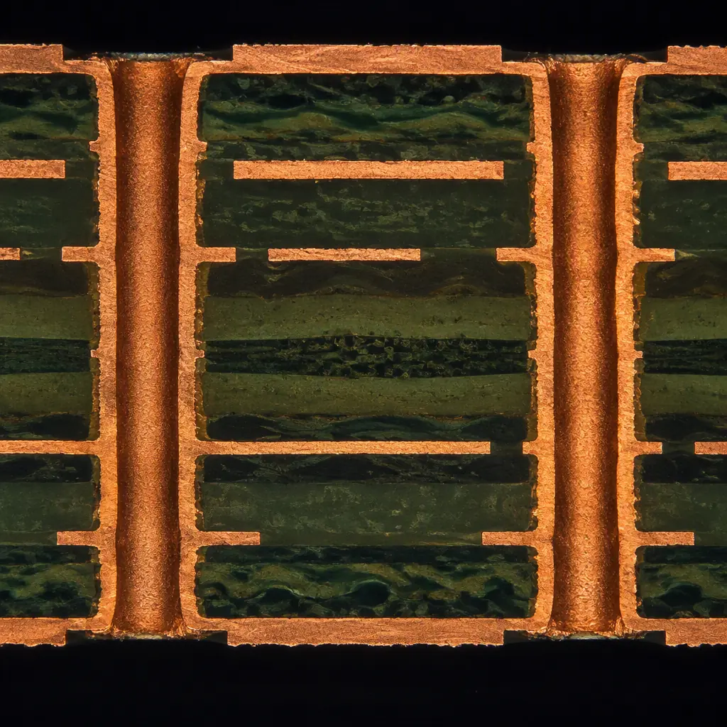
Plated through vias and microvias are the most thermally stressed structures on a printed circuit board, and they are the feature most likely to fail first in a product that cycles between temperature extremes. A via is a copper barrel plated through a hole in a laminate whose coefficient of thermal expansion in the Z-axis is roughly five to seven times that of copper. Every thermal excursion forces the barrel to stretch and compress against the surrounding resin. After enough cycles, the barrel cracks — usually at the knee where it meets the surface pad or an internal plane — and the connection becomes intermittent before it becomes open.
Qualifying that structure is a real test cost, and buyers are frequently asked to pay for it without a clear view of which test answers their question. Three methods dominate: thermal shock testing to IPC-TM-650 Method 2.6.7.2, Interconnect Stress Testing to IPC-TM-650 Method 2.6.26, and HATS. They measure overlapping but different things, on different timescales, at different costs. This article lays them out side by side so the specification decision is deliberate. At Huaxing PCBA we run up to 32 layers with blind, buried and stacked microvias, and layer count is the single best predictor of which test a programme actually needs.
Why Vias Fail Under Thermal Cycling
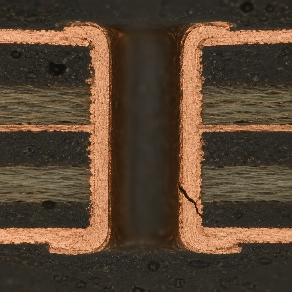
The failure mechanism is a fatigue problem driven by a mismatch in thermal expansion. FR-4 and similar laminates expand approximately 50 to 70 parts per million per degree Celsius in the Z-axis, depending on resin content and glass style, while electrodeposited copper expands at roughly 17 ppm per degree Celsius. A via barrel is mechanically bonded to the resin through the hole wall and to the copper planes it penetrates, so when the board expands more than the barrel, the barrel is forced to strain.
The strain concentrates rather than distributing evenly. The highest-stress locations are the knee of the barrel where it transitions to the surface land, the point where the barrel meets an internal power or ground plane, and any region of thin or poorly levelled copper plating. This is why failure analysis so often finds a circumferential crack at the barrel-to-pad knee rather than a crack in the middle of the hole. It is also why plating thickness and plating uniformity are the two process parameters that most directly determine via reliability — a barrel that is 20 micrometres thick all the way through will outperform one that is 25 micrometres at the surface and 12 micrometres in the middle, regardless of what the drawing claims.
Geometry raises the risk further. Thick boards force a longer barrel, and strain scales with length. Backdrilled vias and via-in-pad structures introduce transitions that concentrate stress. Stacked microvias place multiple plated interfaces in series, so a single intermetallic or plating defect propagates through the stack. High layer counts mean more internal planes, and therefore more locations where the barrel is mechanically constrained. The practical consequence is that a 20-layer board with stacked microvias is not simply a larger version of a 4-layer board from a reliability standpoint — it is a different qualification problem, and it deserves a different test.
Key Takeaway: Via failure is Z-axis CTE fatigue concentrated at barrel knees and plane interfaces. Anything that lengthens the barrel, thins the plating or adds constrained interfaces increases the risk — and that risk profile determines which test will actually detect it.
The Three Qualification Tests, Defined
The three methods differ in how they apply thermal load and, more importantly, in how they detect that a via has begun to fail. That second difference is what determines which test sees a marginal board.
Thermal shock to IPC-TM-650 Method 2.6.7.2 is the traditional approach. Coupons or whole panels are transferred between two chambers or baths held at fixed temperature extremes — commonly −55 °C to +125 °C — with a short dwell at each extreme. The transition is rapid, which is the "shock" part of the name. The specimen is not electrically monitored during the test; the assessment is destructive. After a specified number of cycles, the boards are sectioned and the barrels are examined microscopically for cracks, barrel separation and plating voids. The end result is a pass or fail at a given cycle count, plus a microsection report.
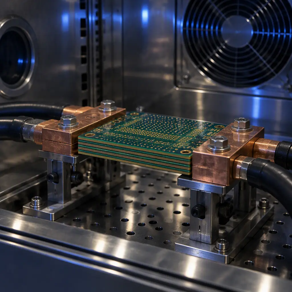
Interconnect Stress Test to IPC-TM-650 Method 2.6.26 takes a different route. IST uses a dedicated coupon — a plated structure built on the same panel as the production boards — and passes a current directly through the via chain. The current both heats the coupon and acts as the sensing element: as the test cycles the coupon between a low and a high temperature set point, the system continuously monitors the resistance of the via chain. Because resistance is measured in situ throughout the test, IST detects the earliest stage of barrel cracking as a measurable increase, rather than waiting until a crack is large enough to see in cross-section. IST is also much faster, because the coupon is heated electrically in seconds rather than being moved between chambers.
HATS — Highly Accelerated Thermal Shock uses the same electrical-heating and resistance-monitoring principle as IST but applies a more aggressive thermal profile, with faster ramp rates and a wider excursion. It is a stress-screening and margin-finding tool rather than a pass-or-fail qualification test: the point is to drive a structure to failure quickly to establish how much margin exists, or to screen a batch for latent defects.
Test Parameters Side by Side
The table below consolidates the parameters that matter when writing a specification and budgeting a programme. Figures are typical values for standard commercial test services and are the ones we work with when advising customers.
| Parameter | Thermal Shock (IPC-TM-650 2.6.7.2) | IST (IPC-TM-650 2.6.26) | HATS |
|---|---|---|---|
| Coupon | Whole panel or production coupon | Dedicated IST coupon on production panel | Dedicated coupon |
| Typical temperature range | −55 °C to +125 °C | Set points typically 25 °C to 150 °C | Wider excursion, faster ramp |
| Cycle time | 20–60 min per cycle | 3–6 min per cycle | Under 3 min per cycle |
| Typical cycle count | 100–500 cycles | 150–1,000+ cycles | Varies — run to failure |
| Typical duration | 4–20 days | 1–3 days | Hours to 2 days |
| In-situ monitoring | No | Yes — continuous resistance | Yes — continuous resistance |
| Pass/fail metric | Microsection crack assessment | Resistance change threshold | Cycles to failure |
| Destructive | Yes | Coupon destroyed; production boards untouched | Coupon destroyed |
| Best use | Formal qualification evidence, customer acceptance | Fast process validation and material qualification | Margin assessment, screening |
Two practical consequences follow from this table. First, IST is roughly an order of magnitude faster than conventional thermal shock for an equivalent number of cycles, because the coupon is heated electrically and the cycle time is minutes rather than tens of minutes. Second, and less obviously, IST is more likely to flag a marginal board. A thermal shock test that ends in a microsection assessment can only report a crack that is large enough to be visible in a polished cross-section at the sampled locations. A resistance-based test reports the first measurable increase in barrel resistance, which occurs when a crack has propagated through only part of the barrel circumference. The same board can pass thermal shock and fail IST, and the IST result is the more conservative — and usually more accurate — answer.
Procurement Note: If a supplier only offers thermal shock, ask whether they monitor resistance during the test or assess by microsection only. Microsection assessment is a sampling method applied after the fact, and a crack at an unsampled barrel will not be found.
Reading the Results: Resistance-Change Criteria
Because IST and HATS are resistance-monitored tests, the acceptance criterion is a threshold rather than a visual judgement, and getting the specification right matters as much as running the test. The conventional criterion is a resistance increase of 10 percent over the initial baseline value for the monitored via chain, sustained rather than transient, or a specified absolute increase in some specifications. The number chosen should reflect the application: a board carrying a high-current power path has a very different sensitivity to a 10 percent increase than a board carrying a low-level signal, though the industry default remains 10 percent for general qualification.
The output of an IST run is a resistance-versus-cycle curve, and reading its shape tells you more than the endpoint. A curve that is flat for the whole run and then steps up sharply indicates a single dominant failure event — one barrel cracking through. A curve that drifts gradually upward before the step indicates progressive barrel fatigue across many vias, which is the expected signature of a well-behaved structure near its limit. A curve that steps up early and then continues stepping indicates multiple independent failures, meaning the via population is not uniform — a plating uniformity problem rather than a design limit. A structure that survives the specified cycle count with a flat curve has margin that has not been quantified; one that fails at a known cycle count has margin that has been measured.
This is where the test choice interacts with the evidence you actually need. If the requirement is to demonstrate compliance with a customer specification or a standard, thermal shock to IPC-TM-650 2.6.7.2 with a microsection report is the conventional evidence and is what most audit programmes expect to see. If the requirement is to know how much margin a process or a material change has, IST gives you the number, faster, and with better sensitivity. If the requirement is to screen a production batch or establish where a design breaks, HATS is the tool. Many programmes use IST for development and thermal shock for formal qualification, which is a defensible combination — our coverage of microvia reliability and IST goes deeper on the microvia case specifically.
Which Test Should You Specify?
The decision follows from product class and layer count. There is no single correct answer, but the mapping is stable across programmes.
Consumer and Short-Life Commercial Products
For a product with a three-to-five year service life in a benign thermal environment, formal via qualification is usually unnecessary. The relevant risks are assembly-induced defects rather than long-term fatigue, and those are caught by thermal shock screening or by assembly-level reliability testing. If a qualification is required by a customer, thermal shock to IPC-TM-650 2.6.7.2 at 100 cycles with a microsection assessment is generally sufficient evidence. IST changes little at this class and is not worth the added specification overhead.
Automotive and Industrial Electronics
Automotive modules see real thermal cycling — engine-adjacent, under-hood and powertrain electronics in particular — and the service life expectation is ten to fifteen years. This is the class where IST earns its place, because it gives a quantified margin number that can be tracked across process changes, laminate lots and plating chemistry revisions. A practical specification is IST to IPC-TM-650 2.6.26 with a 10 percent resistance-change criterion, run to a cycle count that reflects the product's thermal mission profile, on coupons from the production panel. Boards that will also be submitted for customer qualification should additionally be characterised by thermal shock so the formal evidence exists.
Aerospace, Defence and High-Layer-Count Infrastructure
At this class the requirement is evidence plus margin plus traceability. High layer counts with backdrilled or stacked microvia structures are exactly the geometry where partial barrel cracks form first and where a microsection-based test can miss them. We recommend dual evidence: IST for the quantified margin and the resistance curve, plus thermal shock to 2.6.7.2 with microsection for formal qualification against the customer or standard requirement. Where the product must demonstrate margin rather than mere compliance, HATS run to failure establishes the failure mode and the cycle count at which it occurs. Our article on backdrilling covers the geometries that raise this risk most, and our IPC-6012 qualification guide covers the acceptance framework these tests feed into.
New Laminate, New Plating Chemistry or New Stackup
Whenever a material or process input changes, the via structure's margin changes with it, and the question is not whether the board passes but whether it passes as comfortably as the previous revision. This is the strongest case for IST specifically, because the resistance curve is comparable between builds and a shift in the curve is visible immediately. Running IST on a coupon from the first panel of a new laminate lot is a low-cost way to catch a reliability regression before a full qualification campaign. Thermal shock is the wrong tool here: it produces a pass or fail, which will not reveal a margin reduction that has not yet reached the failure threshold.
Specifying It in Your PO and Reading the Report
A test specification needs four elements to be actionable: the method and its IPC-TM-650 number, the coupon definition and where it comes from, the thermal profile including temperatures and dwell, and the acceptance criterion including cycle count and the resistance threshold. Stating "IST testing required" without a cycle count or a threshold is not a specification — it is a request for a test to be run, with the acceptance decision left to the supplier.
Sample size and coupon placement matter as much as the parameters. A coupon taken from a different part of the panel than the production boards is not representative of the boards being shipped, and a single coupon from a single panel tells you about that panel rather than about the lot. For a serious qualification we recommend coupons from at least three panels across the lot, with the coupon location recorded, plus retention of the raw resistance-versus-cycle data rather than only the pass/fail verdict. If a supplier provides only a summary verdict with no curve data, ask for the curves.
On the receiving end, the microsection report is the piece that is most often read carelessly. What matters is the plating thickness measurement taken at multiple points around the barrel rather than a single nominal figure, the observation of any barrel-to-pad knee separation, and whether the section was taken at a location known to be high-stress. A thickness measurement quoted as a single number is a summary, not a measurement. Our cross-section report guide explains how to read these reports in detail, and our failure analysis guide covers what to do when a via does fail — including the dye-and-pry and cross-section techniques used to localise the crack. Boards that also face mechanical exposure should be qualified for that separately; our vibration and shock testing article covers the mechanical equivalent of this qualification problem.
Key Takeaway: Thermal shock proves compliance and produces a microsection report; IST measures margin and finds marginal vias that thermal shock misses; HATS establishes where a structure breaks. Development programmes should use IST, formal qualification should use thermal shock, and high-layer-count programmes should use both.
Summary and Next Steps
Via reliability qualification is a specification decision, and the three available tests answer different questions. Thermal shock to IPC-TM-650 2.6.7.2 delivers formal compliance evidence with a microsection assessment. IST to IPC-TM-650 2.6.26 delivers a quantified resistance-based margin measurement in a fraction of the time and detects earlier-stage barrel cracking. HATS drives a structure to failure quickly to establish margin. Matching the test to the product class — thermal shock for consumer evidence, IST for automotive and industrial margin tracking, dual evidence for aerospace and high-layer-count infrastructure — turns an open-ended test budget into a deliberate qualification plan.
At Huaxing PCBA we fabricate multilayer boards up to 32 layers with blind, buried and stacked microvias, and we coordinate via reliability testing with accredited test partners — running coupons from production panels so the test reflects what you actually receive. We provide plating thickness data, microsection reports and raw IST resistance curves on request, and we can build to a specification that names the IPC-TM-650 method, the cycle count and the acceptance threshold. Send your Gerber, stackup and reliability requirement, and our engineering team will respond within 24 hours with a test recommendation, a free DFM review and a quote. You can also read our via technology guide or contact our engineering team to discuss a specific stackup.
