
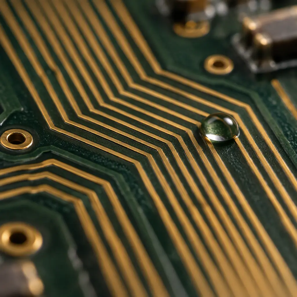
An electrochemical migration failure looks like a manufacturing defect and is usually not one. A fine-pitch assembly passes functional test, ships, and then fails weeks or months later in the field with a low-resistance short between two adjacent conductors. Cross-section or optical inspection finds a dendritic growth bridging the gap. Nothing was assembled incorrectly. The board was contaminated, or wet, or both, and the electrical bias between the conductors did the rest.
The mechanism matters commercially because it is one of the slowest and most expensive failure modes to diagnose after the fact. By the time dendrites are visible the assembly is in the customer's hands, the batch is dispersed, and the investigation has to reconstruct process conditions from months earlier. The three variables that drive it — ionic contamination, moisture and applied bias — are all measurable, and all three can be bounded at DFM and controlled in process. Getting them right costs very little. Getting them wrong is a field-failure programme.

What Electrochemical Migration Actually Is
Electrochemical migration, usually shortened to ECM, is the electrochemical transport of metal ions across a surface or through a bulk material under the combined influence of moisture and electrical bias. The sequence has four stages, and every stage is a precondition for the next.
Condensation or adsorbed moisture forms an electrolyte layer
Below a certain relative humidity the adsorbed water layer on a circuit board is a few molecules thick and effectively insulating. Above it, the layer becomes continuous enough to dissolve ionic species and carry current. This threshold is not a fixed number — it depends on the surface chemistry, the cleanliness of the board and the presence of hygroscopic residues — but it is the single most important gate. A board that never reaches that humidity will not grow a dendrite regardless of how contaminated it is.
Ionic species dissolve into that layer
The contaminants that matter are the ones that ionise readily in water. Flux residues left from inadequate cleaning, plating salts from the fabrication process, handling salts from skin contact, and atmospheric pollutants such as chlorides and sulphates all contribute. Halide ions are the most aggressive because they both increase conductivity and attack the passive oxide that would otherwise slow metal dissolution. This is why chloride contamination is weighted so heavily in cleanliness specifications.
A potential difference drives ion migration
With an electrolyte present, an applied voltage between two conductors causes metal at the anode to dissolve into ions that migrate toward the cathode. There is a threshold voltage below which the process is negligible for practical purposes; published work commonly places the onset for silver systems well under one volt, and copper systems somewhat higher depending on the chemistry and the spacing. The practical reading is that almost any live bias in a humid, contaminated assembly is a candidate, and reducing voltage is rarely the lever you have available.
Metal deposits as a dendritic growth that bridges the gap
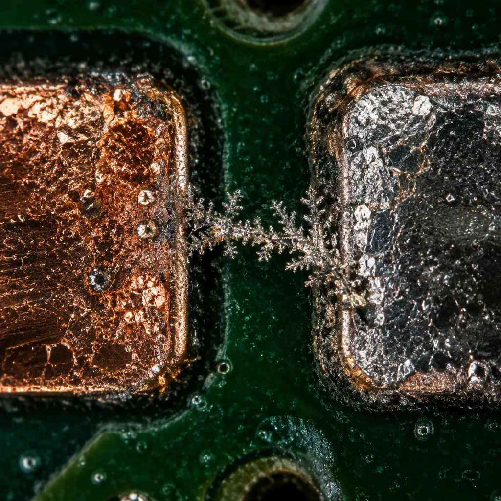
The migrating ions reduce at the cathode and deposit as metal. Because deposition is favoured at points of highest field, the growth is not uniform — it extends as a branching, tree-like filament from cathode toward anode. Once the filament bridges the gap the circuit shorts. At low currents the filament can also carry enough heat to open again, which produces the intermittent faults that make ECM so frustrating to diagnose on a test bench.
Silver Is Not the Only Metal at Risk
ECM is most often discussed in the context of silver, because silver migrates readily at low voltage and is common in conductive adhesives, silver-filled epoxies and some termination finishes. But the mechanism is not silver-specific, and a specification that only bans silver is not a specification against ECM.
| Conductor / Finish | ECM Susceptibility | Practical Note |
|---|---|---|
| Silver (conductive adhesive, sintered joints, terminations) | High — migrates at low bias | The classic case; also hygroscopic residues can accompany silver-filled adhesives |
| Copper (bare or poorly protected traces) | High when exposed and contaminated | Most common in practice; solder mask coverage is the primary control |
| Tin / tin-lead solder | Moderate | Migrates, but the surface oxide layer slows onset compared with bare copper |
| ENIG (gold over nickel) | Low on the gold surface | Risk concentrates at exposed nickel or copper if the gold layer is porous or thin |
| Immersed gold / immersion silver | Low to moderate | Immersion silver is thin and the underlying metal can become the migrating species |
| OSP (organic solderability preservative) | Low before assembly | The coating is consumed in reflow; post-assembly cleanliness governs |
Key Takeaway: ECM is not a silver problem, it is a contamination-and-moisture problem that happens to be worst with silver. If your cleanliness and humidity budget is sound, you can use silver-filled materials in a fine-pitch assembly. If your cleanliness budget is not sound, switching away from silver removes the most sensitive species but leaves the mechanism intact for copper.
The Three-Variable Budget
Because ECM requires all three of contamination, moisture and bias, an assembly survives if any one of them is held low enough. In practice bias is set by function and is the hardest to change, so the control levers are cleanliness and environmental exposure.
| Variable | Typical Control | How It Is Specified or Measured |
|---|---|---|
| Ionic contamination | Post-assembly cleaning, flux chemistry selection | Roses (resistivity of solvent extract) or ion chromatography; expressed in ug NaCl equivalent per square centimetre |
| Moisture exposure | Conformal coating, potting, enclosure sealing, desiccant in transit | Coating coverage and thickness verification; humidity-thaw and damp-heat test conditions |
| Applied bias | Reduce potential difference where the design allows | Spacing rules, guard traces, avoiding high-voltage adjacency at fine pitch |
| Surface geometry | Increase conductor spacing, remove exposed metal | Design rule checking against voltage-versus-spacing tables |
The interaction is what makes single-variable fixes unreliable. A board that is only slightly contaminated and only briefly moist may survive decades. The same board in a condensing environment with a poorly cleaned no-clean flux — a combination that looks acceptable on each count taken alone — can fail within weeks. Procurement discussions that argue about one number without the other two usually miss the actual risk.
Test Methods and What They Prove
There is no single test that proves an assembly is immune to ECM. The available methods each probe a different part of the budget, and the credible approach is to combine a cleanliness measurement with an environmental stress test.
| Method | What It Measures | Typical Use |
|---|---|---|
| ROSE / resistivity of solvent extract | Total ionic contamination as a single number | Incoming and in-process cleanliness check; fast, but does not identify which ions are present |
| Ion chromatography | Species-by-species ionic concentration | Failure investigation and process qualification; the halide breakdown is the actionable part |
| Surface insulation resistance (SIR) | Leakage resistance across a patterned test coupon under bias | The most direct proxy for ECM tendency; run under humidity and temperature with bias applied |
| Damp heat, steady state | Long-duration moisture at constant temperature | Qualification of coating systems and assemblies for humid environments |
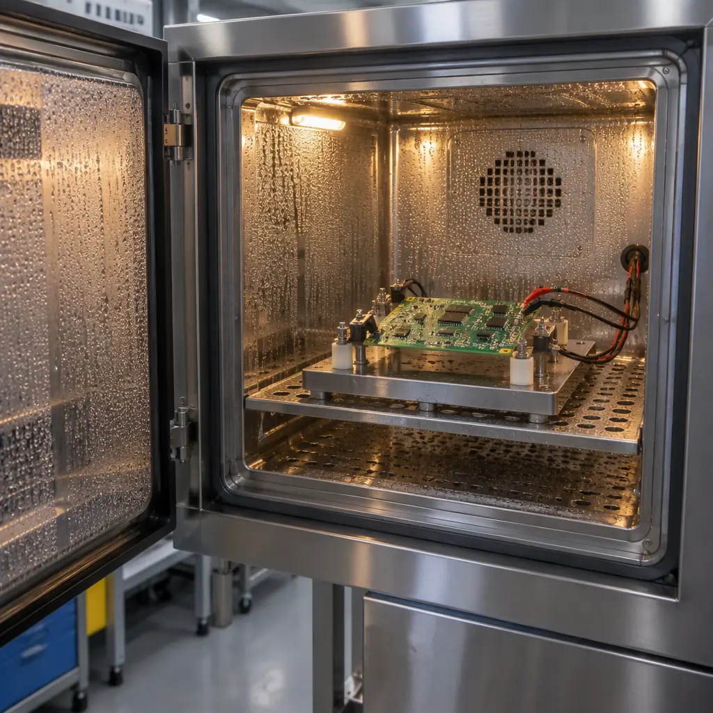
| Humidity with bias (HAST or equivalent) | Accelerated moisture plus electrical bias | Accelerated screening; the bias is what makes it relevant to ECM specifically |
| Thermal cycling with humidity | Condensation driven by temperature transitions | Assemblies whose service profile includes repeated dew-point crossings |
The detail that separates a useful test from a decorative one is whether bias is applied during the humid phase. An unbiased damp-heat test measures moisture uptake and corrosion resistance. It does not measure migration, because migration requires an electric field. A test programme that runs humidity without bias and reports compliance has measured a different property than the one the failure mode depends on. Where a customer asks for evidence against ECM specifically, the test report should show the applied voltage, the conductor spacing on the test pattern and the duration of biased exposure. Our guide to burn-in and environmental stress screening covers the equipment and profile side, and the broader inspection methods used to confirm failures are covered in AOI, X-ray and SPI inspection.
Prevention: What Actually Works
Prevention follows the budget. Hold two of the three variables low and the third becomes much less critical. Five measures account for most of the reliability improvement in practice.
Match the flux chemistry to the cleaning decision
No-clean flux is designed to leave residues that are benign under the conditions the assembly will actually see. That assumption holds in a dry, enclosed, well-ventilated product and fails in a condensing or humid one. If the assembly is going into an outdoor, marine, washdown or condensing environment, no-clean is a decision that needs evidence, not a default. Where residues are hygroscopic or contain halides above the specified limit, cleaning after assembly is the practical answer.
Verify cleaning rather than assuming it
Cleaning processes lose effectiveness gradually as wash chemistry ages, nozzles clog and fixtures accumulate residue. A one-off validation at process introduction does not hold for two years. Periodic ROSE or ion chromatography on production boards, with a defined limit, converts cleaning from a process step into a controlled one. For fine-pitch assemblies with high component density, the under-component region is where cleaning is hardest and where residues persist.
Coat the surfaces that will see moisture
Conformal coating interrupts the mechanism by blocking the electrolyte path, provided coverage is complete. The failure mode to design against is incomplete adhesion at edges, at the base of tall components and across sharp features, where a capillary gap lets moisture travel under the coating. Coating is not a substitute for cleanliness — a contaminated board under a coating can still migrate along the interface — but a clean, well-coated board is robust. The acrylic, silicone and parylene trade-offs are set out in our conformal coating guide.
Design spacing against the voltage actually present
Design rules that set a single minimum spacing for the whole board ignore the fact that ECM susceptibility rises with field strength. The conductors at risk are the closely spaced pairs carrying the largest potential difference. Increasing spacing only on those nets, adding a guard trace, or routing a high-voltage node away from fine-pitch signal areas costs almost nothing at layout and removes the most aggressive cases.
Control handling and transit moisture
Bare-handed handling deposits salts directly onto the surface, and chloride from fingerprints is exactly the species the mechanism prefers. Glove and ESD discipline during assembly, inspection and packing is a real control, not a formality. In transit, humidity indicator cards and desiccant in a sealed barrier bag prevent the assembly from arriving damp, which matters most for boards that will be stored before final assembly. The storage side is covered in our guide to PCB storage and moisture control.
What to Write Into the Purchase Specification
ECM requirements that live only in a conversation do not survive a supplier change or a personnel change. Four lines in the specification do the work.
Procurement Tip: Specify four things explicitly. First, the cleanliness limit and the method used to verify it — for example a maximum ionic contamination expressed in micrograms of sodium chloride equivalent per square centimetre, measured by ROSE or ion chromatography, with the test frequency stated. Second, the maximum halide content permitted in flux residues if no-clean is used. Third, whether conformal coating is required, which surfaces must be coated and how coverage will be verified. Fourth, the environmental test the assembly must pass, including the applied bias during the humid phase. A specification that names the method and the limit is auditable; one that says clean and coated is not.
The commercial argument for doing this is straightforward. ECM failures appear after shipment, are expensive to diagnose, and are frequently attributed to the manufacturer regardless of whether the root cause was a design decision, a process excursion or a field environment outside the original specification. A supplier who can show a measured cleanliness number and a biased humidity test result is far better protected than one who can only assert that the process is controlled — and the customer gets a defensible reliability position rather than an argument.
The Bottom Line
Electrochemical migration requires ionic contamination, moisture and electrical bias together, and removing any one of them from the equation removes the failure mode. Bias is set by the circuit and is usually fixed, so the practical levers are a verified cleanliness level and environmental protection matched to the service conditions. Both are inexpensive to specify at the start and very expensive to retrofit after a field failure. The companies that avoid ECM are not using exotic materials; they are measuring cleanliness instead of assuming it, and testing under bias instead of testing dry.
At Huaxing PCBA we measure ionic cleanliness on production boards against an agreed limit, hold ion chromatography for failure investigation, run biased humidity testing on assemblies specified for humid or condensing environments, and record flux chemistry and cleaning parameters in the process record for every lot. Where a design puts fine-pitch conductors close to a large potential difference, our DFM review flags it before the board is released. Read our conformal coating guide or contact our process engineering team to review your reliability requirements before production.
