
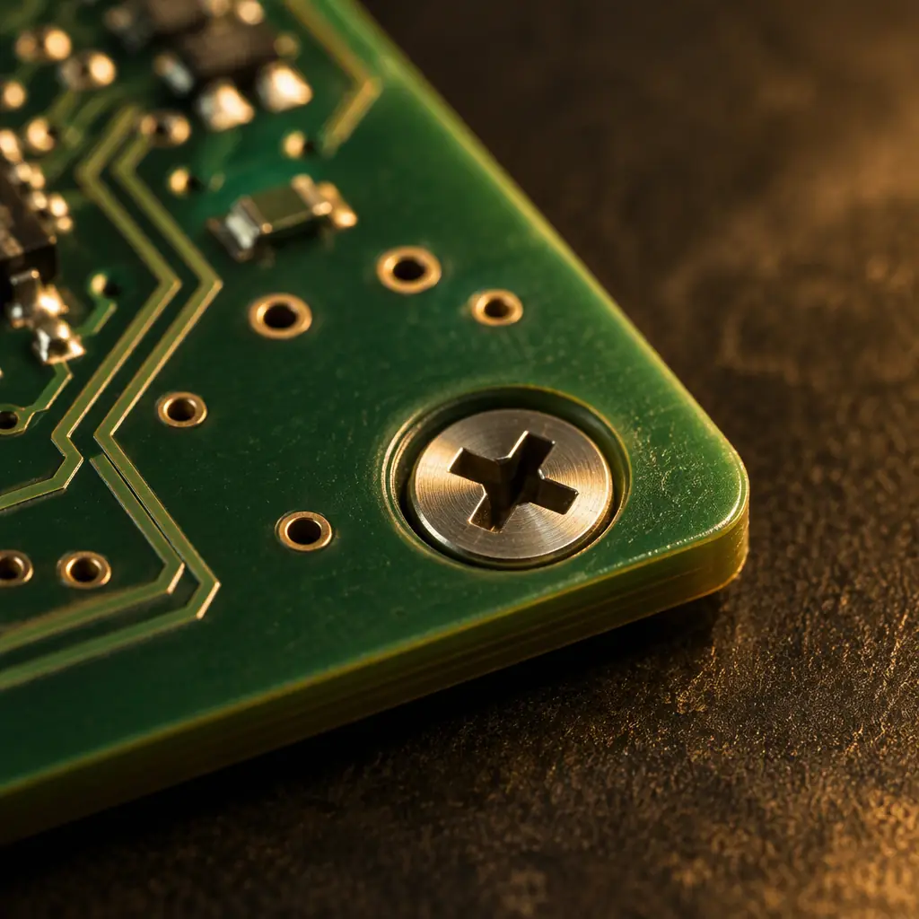
A printed circuit board stops being a purely electrical object the moment a fastener, a housing rib, a connector or a heat spreader has to sit against it. At that point the board carries mechanical geometry: countersinks that let a flat-head screw finish flush, counterbores that keep a screw head below the surface, depth-routed pockets that create clearance, cavities that hold an embedded component, and castellated edges that let one board solder onto another.
These features are milled, not plated, and they are where quoting and capability conversations go wrong most often. A design that holds a 0.10 mm tolerance on copper etching does not automatically hold the same tolerance on a depth-controlled cut, because the cut is referenced to a surface that itself moves within the board's finished-thickness range. Understanding that distinction is the difference between a first-article pass and a costly re-spin.
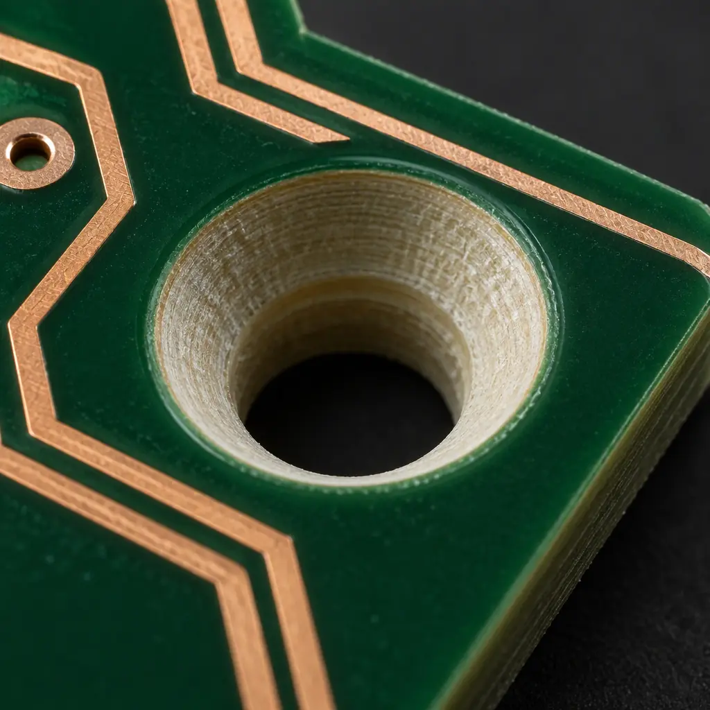
What Counts as a Machined Feature on a PCB
The mechanical features a fabricator produces by material removal, as opposed to etching or drilling, fall into a small, well-defined set. Each one is quoted, inspected and tolerance-controlled differently, so it helps to name them precisely on the drawing rather than relying on a note that says "machine as required."
- Countersink. A conical cut at the top of a through-hole so a flat-head screw seats flush with the board surface. Defined by the included angle (82°, 90° or 100°), the major diameter, and the depth.
- Counterbore. A flat-bottomed cylindrical recess with a coaxial through-hole, used to sink a socket-head or pan-head screw below the surface.
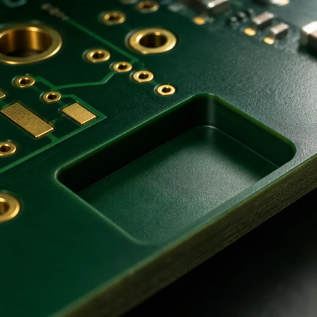
- Depth-routed pocket. A milled recess of controlled depth, leaving a webbing of material beneath it. Used for clearance, potting, or to seat a component.
- Cavity or embedded pocket. A pocket deep enough to house a component inside the board thickness, often combined with lamination around an insert.
- Edge chamfer. A bevel along a board edge, frequently specified for connector mating or to remove a burr where the board slides into a rail.
- Castellation. Half-plated holes at the board edge so a module can be soldered down onto a carrier. These are plated as well as drilled, but they are usually called out alongside machined edge features.
Countersink Design Rules
A countersink is specified by three numbers: the head angle of the screw it must accept, the major diameter at the board surface, and the depth of the conical seat. Getting these wrong is the most common machined-feature error, because the numbers are not independent — the depth is implied by the angle and the diameter, and specifying all three as free values creates an over-constrained callout that no fabricator can inspect cleanly.
| Screw | Head Angle | Typical Sink Ø | Depth (typ.) | Depth Tol. |
|---|---|---|---|---|
| M2 flat head | 90° | 4.0 mm | 1.20 mm | ±0.10 mm |
| M3 flat head | 90° | 6.0 mm | 1.65 mm | ±0.10 mm |
| M4 flat head | 90° | 8.0 mm | 2.20 mm | ±0.10 mm |
| #4-40 flat head | 82° | 0.245 in | 0.055 in | ±0.004 in |
Two process rules matter more than the arithmetic. First, a countersink that reaches into a copper pour will expose the laminate beneath the bevel and can bridge to the sink wall if the surface is plated — so a plated countersink needs a defined keep-out on the copper layer, and an unplated countersink needs the hole called out as non-plated. Second, the minimum remaining wall between the sink edge and any adjacent conductor is governed by your clearance rules, not by the machining tolerance, and it is the check that most often forces a layout change rather than a process change.
Where the sink sits close to a board edge, the same shearing and handling concerns that drive edge finish selection apply. If the design also carries edge plating and castellated features, keep the countersink clear of the plated wall so the two operations do not fight for the same material.
Counterbores, Pockets and Depth-Controlled Milling
A counterbore or a depth-routed pocket is harder to hold than a countersink, because the tolerance is referenced to the board surface on the side the tool enters, while the feature's function often depends on the material remaining on the far side. On a board whose finished thickness carries a ±10% tolerance of its own, the webbing under a pocket inherits the sum of both.
Three design decisions drive whether a depth-controlled feature is manufacturable at reasonable cost:
- Reference the depth to the correct side. State whether the depth is measured from the tool-entry surface or defined as a minimum remaining webbing. The second form is more robust and is what a competent fabricator will recommend when the webbing is structural.
- Keep the webbing thick enough. As a working rule, leave at least 0.30 mm of remaining material beneath a pocket that is not otherwise reinforced; below that the board becomes prone to local warpage and the pocket floor can telegraph through during reflow.
- Avoid sharp internal corners. A milling tool has a radius. Internal corners smaller than the cutter radius force either a larger tool path or a secondary operation, both of which raise cost. Specify a corner radius equal to or greater than the tool radius and let the tool decision be the fabricator's.
Tolerances a Fabricator Can Actually Hold
Capability is not a single number. Each machined feature has its own achievable tolerance, and the achievable value tightens or loosens with board thickness, feature size and the position of the feature relative to the panel edge. The values below are what a well-equipped fabricator holds as a matter of routine on a standard FR-4 build; tighter values are possible but should be discussed at quote stage rather than assumed.
| Feature | Routine Tol. | Drives the Limit |
|---|---|---|
| Countersink diameter | ±0.10 mm | tool geometry and entry surface flatness |
| Countersink depth | ±0.10 mm | board thickness variation |
| Counterbore diameter | ±0.10 mm | cutter runout |
| Pocket depth | ±0.15 mm | Z-axis control and thickness stack |
| Feature position (X-Y) | ±0.10 mm | drill/mill registration |
| Edge chamfer width | ±0.15 mm | routing depth control |
These numbers only hold when the machining is referenced to a datum that the fabricator controls. A drawing that dimensions a pocket from a routed board edge, where the edge itself is only held to the general routing tolerance, stacks two tolerances into the feature position. Dimension machined features from a drilled datum hole or an established tooling hole, and the achievable position tolerance improves substantially. The same principle governs how manufacturing tolerances are stacked across the rest of the board.
Design Checks Before You Release the Drawing
Five checks catch the overwhelming majority of machined-feature problems before the drawing leaves your desk:
- Is the depth referenced to a datum the fabricator controls, or to a routed edge that carries its own tolerance?
- For every countersink, is the head angle stated once and the diameter/depth derived, rather than all three listed as free values?
- Does any countersink or counterbore break into a copper pour or a plated wall without a stated keep-out?
- Is the remaining webbing under each pocket at least 0.30 mm, and is it stated as a minimum rather than implied?
- Do internal pocket corners carry a radius at least equal to the cutter radius, so no secondary operation is silently required?
If all five answer cleanly, the feature set is manufacturable at standard process capability. If any one does not, correcting it on the drawing costs nothing; correcting it after the first article costs a tooling change and a schedule slip. The discipline mirrors what a drilling-tolerance review does for holes — you are checking that the tolerances you wrote are ones the process can actually inspect and hold.
Cost and Lead-Time Impact of Machined Features
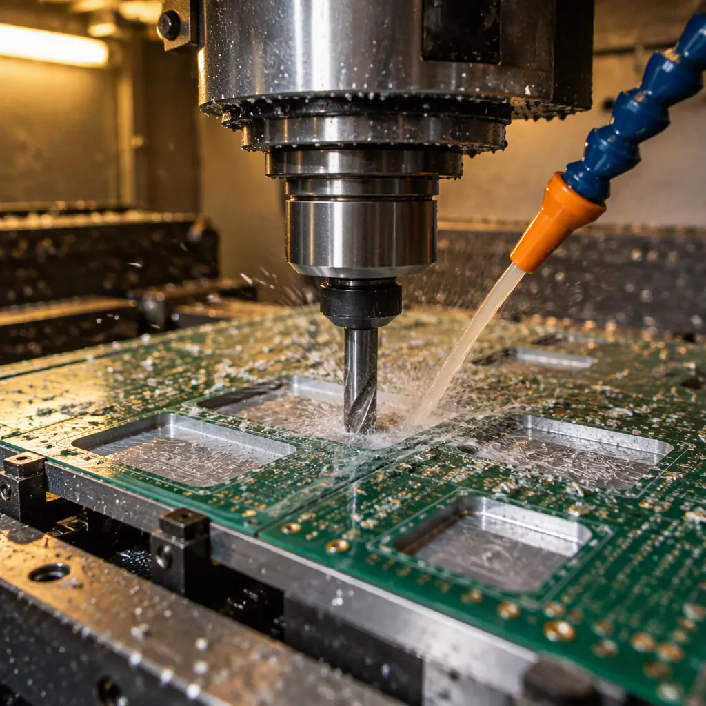
Machining is a serial, per-board operation, so its cost scales with the number of operations and the number of boards, not with panel area the way etching does. The practical effect is that machined features are cheap in engineering terms and expensive in unit terms at volume.
- Countersinks and counterbores add a small per-hole cost and are usually absorbed into the tooling charge at prototype volume; at high volume they become a visible adder per board.
- Depth-routed pockets add setup plus per-board mill time, and they typically require a dedicated program that is quoted as non-recurring engineering.
- Cavities and embedded pockets interact with lamination, so they change the build sequence and carry both tooling and process cost.
- Edge chamfers and castellations are usually priced with the routing and edge-plating operations rather than as a separate machining step.
The lead-time effect is gentler than the cost effect, but it is real: any adding of a machining operation inserts a queue step that a plain board does not have. Where a program is schedule-critical, consolidating features onto one operation and keeping pockets shallow enough to mill in a single pass both reduce the number of queue steps.
Specifying Machined Features in Your Fab Drawing
The callout format is what removes ambiguity. State the feature type, the controlling dimension, the tolerance, and the datum the tolerance is referenced to, in that order, on a detail view rather than in a general note. For a countersink, that reads as "countersink, 90° included, Ø6.0 mm major, depth referenced to surface A, ±0.10 mm." For a pocket, it reads as "mill pocket to 0.40 mm minimum remaining webbing, corner radius R1.0 minimum, positioned from datum hole D1, ±0.10 mm."
When a machined feature sits alongside depaneling and edge treatment, it also affects how the board is separated from its panel. Panel design and depaneling method determine whether a milled feature can be produced before or after separation, so the two conversations belong together at quote stage.
At Huaxing PCBA machined features are quoted with a detail drawing review at the front end, so countersinks, counterbores, pockets and cavities are confirmed against process capability before the order starts. We hold ±0.10 mm on countersink and counterbore geometry and ±0.15 mm on depth-routed pockets as routine, across builds up to 32 layers, and we flag any callout that cannot be inspected as written. Send your Gerber and mechanical drawing for a quote or talk to an engineer about the machined features on your board.
