
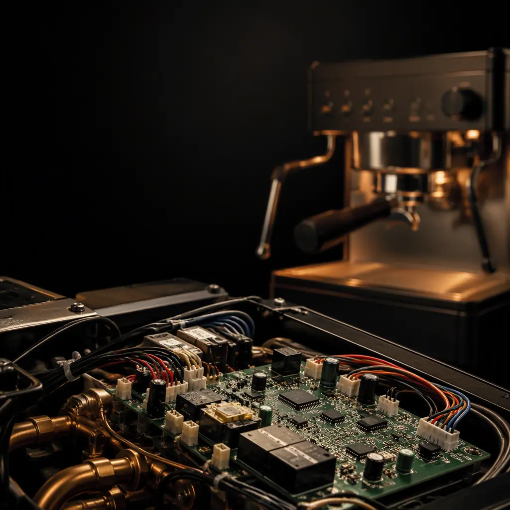
Professional espresso machines are small, wet, hot, and sold in thousands of units a year. Which is exactly why the electronics rarely get the engineering attention they deserve. The boiler control board is the highest-failing component in a machine that ships, and it fails for predictable reasons: relays sized too small, PID gains that never get tuned, creepage clearance on the mains side measured in millimetres instead of millimetres, and a sensor that sits too far from the water it is trying to measure. This guide walks through how a reliable machine PCB is actually specified.
At Huaxing PCBA we assemble mixed-signal and power boards for appliance and commercial-equipment OEMs every week, running 8 SMT lines with 0201 to 0.3 mm BGA capability and full functional test. The rules below are the ones you would apply naming no specific vendor, they hold for any factory that treats a 230V control board as a safety-critical assembly rather than a hobbyist relay board.
1. The Board Must Control Four Very Different Worlds
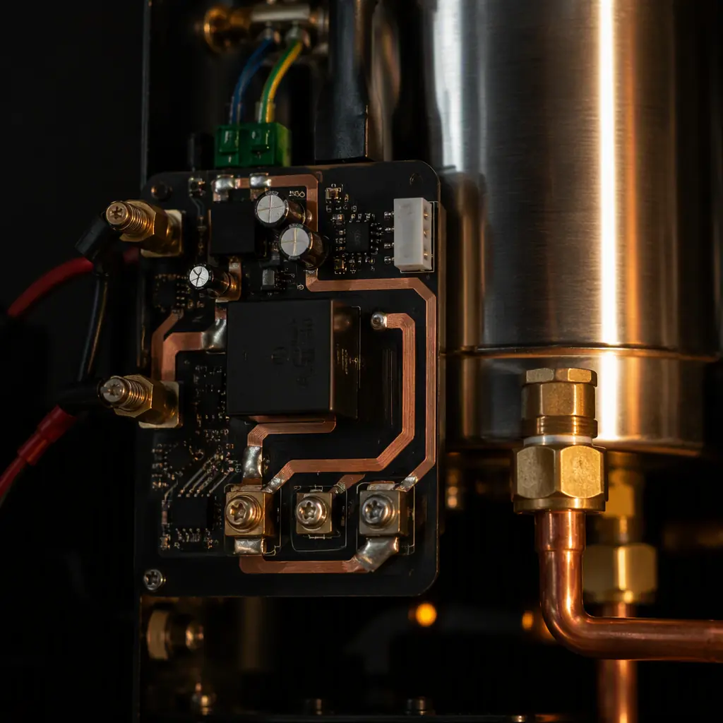
Most coffee-machine failures trace back to one design: a single board expected to handle kilowatts on one side and microvolts on the other. Break the machine down and you get four distinct electrical zones that all land on one PCB:
| Zone | Typical Load | Design Risk |
|---|---|---|
| Heater / boiler | 1.2–1.8 kW at 230V | High-current switching, contact wear, thermal coupling |
| Vibration pump | 52–60 W, 45–90 Hz drive | Inductive kickback, EMI from sparking |
| Sensors | NTC/PT100, 5V exciter | Noise injection from power zone |
| HMI / communications | 3.3V MCU, touchscreen, RGB | ESD, ground loops, LCD EMI |
The answer is almost never four separate boards, it is one board, four cleanly partitioned islands, each with its own local ground stitching and a single-point connection to the mains earth. That is what keeps a 1.6 kW heater from picking up the 3.3V temperature reading.
2. PID Temperature Control, Where Machines Win or Fail
A good shot is a stable temperature. PID control on the boiler is where that stability is made or lost, and most OEM boards get the loop tuning wrong because the plant changes as the heater cycles. A 1.4 kW element in a 200 mL boiler has a time constant of only a few seconds, so a poorly damped integral term will overshoot by 8–10°C on every brewing cycle.
Place the Sensor, Then Loop Around It
An NTC glued to the boiler wall reads the metal, not the water. A probe in the water stream reads the brew temperature but reacts ~2 s later. Most OEMs compromise with a sensor in a thermowell in the water path and accept that lag. Whatever you choose, the PID gains must be tuned against that physical arrangement, never against a datasheet example.
Use Bang-Bang for Preheat, PID Only for the Shot
During heat-up, proportional control is overkill. Run a simple on/off hysteresis until within 2°C of target, then hand off to a low-integral PID for the shot window. This cuts time-to-ready and eliminates the phase of endless oscillation that makes a machine feel "hunting" to the user.
Feedforward the Flow
When the pump starts, cold water enters and the heater must dump energy immediately. A feedforward term keyed to pump-on (a small fixed duty boost for the first ~4 s) removes the temperature dip that ruins the first extraction. This is a one-line change that dramatically improves shot consistency.
3. Mains Safety, Creepage, Clearance and Isolation
This is non-negotiable, and it is where coffee-machine boards most often violate the standard. On a 230V mains board the creepage requirement (distance along the surface) for reinforced insulation is typically 5.5 mm, and clearance (through air) around 4.0–5.0 mm depending on the IEC category. A board with 2 mm between the live heater trace and an SELV sensor trace is a latent shock hazard and will fail a mandatory EMC/safety pre-cert. If you are entering European (CE) or UK (UKCA) markets, that certification is not optional.
Cut Isolation Slots, Do Not Rely on Solder Mask Alone
Soldermask does not count toward creepage. Where the mains zone meets the control zone, cut an actual routed slot and keep the divider ≥ 4 mm of air. This is a cheap router operation that saves a full safety redesign later.
Isolate the Control Supply
Run the 3.3V control domain from a galvanically isolated AC-DC module (or a dedicated isolated supply) rather than a capacitive dropper. A capacitive dropper is affordable but gives no galvanic isolation, so the "5V" logic node can float at mains potential during a fault, an unacceptable condition for a product touched by users.
Switch the Heater With a Relay, and Spec the Relay Right
Relay contact life is rated in operations, and a coffee machine may switch the heater many thousands of times over its life. Specify a relay with a contact rating comfortably above the inrush (a 1.8 kW element draws ~8 A steady but a cold element can surge 15–20 A on turn-on). Use an RC snubber across the contacts and phase the switching to the AC zero-crossing to extend contact life dramatically.
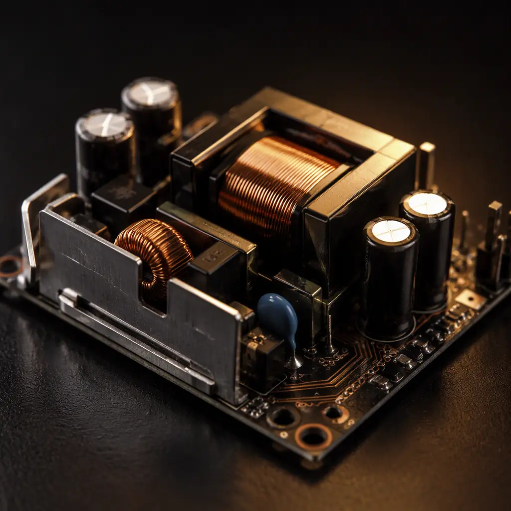
Powering and filtering this zone correctly is the same problem you see in any mains-powered board, see our SMPS layout and PCB design guide and our EMC/EMI compliance guide for the mains-facing details that carry over directly.
4. EMI, ESD and the Sensor That Refuses to Be Quiet
The vibration pump is the EMI villain. Its commutator switches 50–60 W of inductive load several hundred times a second, and the resulting broadband bursts couple straight into the temperature sensor trace if you route them as neighbours. The smoke test here is a 3:1 board, not a bench-friendly one.
Keep the Analog Sensor Trace Short and Guarded
Route the NTC trace on the control island, short and with a ground guard on both sides. Never let it cross under the pump or heater trace. A 1 kΩ series resistor plus a 10 nF filter cap at the ADC input buys acceptable noise immunity for a signal that changes maybe 0.5 Ω per 0.1°C.
Add ESD Protection on Every External Interface
The touchscreen, USB service port, and any connector an operator can reach needs ESD protection to IEC 61000-4-2. A TVS diode at each I/O is standard. A board that fails ESD in the field is a board you will be recalling.
Conformal Coat for the Water, Steam and Sugar
Once a board sits near a brew group, condensation and steam are inevitable. A few microns of acrylic conformal coating protects against condensation and the occasional slosh. This is cheap insurance on any appliance board, see our conformal coating guide for the material and thickness trade-offs.
5. Single Board vs. Modular, A Procurement Decision
For a machine family, the modular vs. single-board decision shapes cost and serviceability. A single board saves BOM cost and interconnection, but a boiler failure takes the whole control board with it. A split design, one power/heater board, one HMI/display board, makes the field-replacement part cheaper and lets you share the HMI across several SKUs. The catch is more connectors, more assembly steps, and more points for contamination.
For a product shipping 5,000–20,000 units a year, the connector cost of a modular design is usually outweighed by the lower service cost of a $10 replacement HMI board versus a $60 whole-control board. Work the arithmetic with your actual volumes before you lock the architecture.
If your board is mixed-signal with 0201 passives and a 0.3 mm pitch BGA, our assembly lines handle it. And we are strict about reflow and inspection when the board carries a live mains zone. See our mixed-signal PCB design guide and our reflow soldering profile guide for the process side.
Summary, What a Durable Coffee Machine PCB Demands
The board is the keep-alive of a machine that lives in steam, switches kilowatts, and has to hold a 0.5°C temperature band shot after shot. Win it with a hard power/control partition, a relay and snubber sized for real inrush, creepage slots measured against IEC requirements, a correctly placed and tuned PID loop, and ESD/conformal protection on every user-facing surface.
At Huaxing PCBA we assemble mixed-signal and mains-referenced control boards to IPC Class 2/3 under ISO 9001, IATF 16949 and UL. Our 18,000 m² Shenzhen facility runs 8 SMT lines and 4 DIP lines with AOI, X-ray, SPI and ICT/FCT in-line. Send your design files for a free DFM review, or talk to our engineering team about your appliance control board.
