
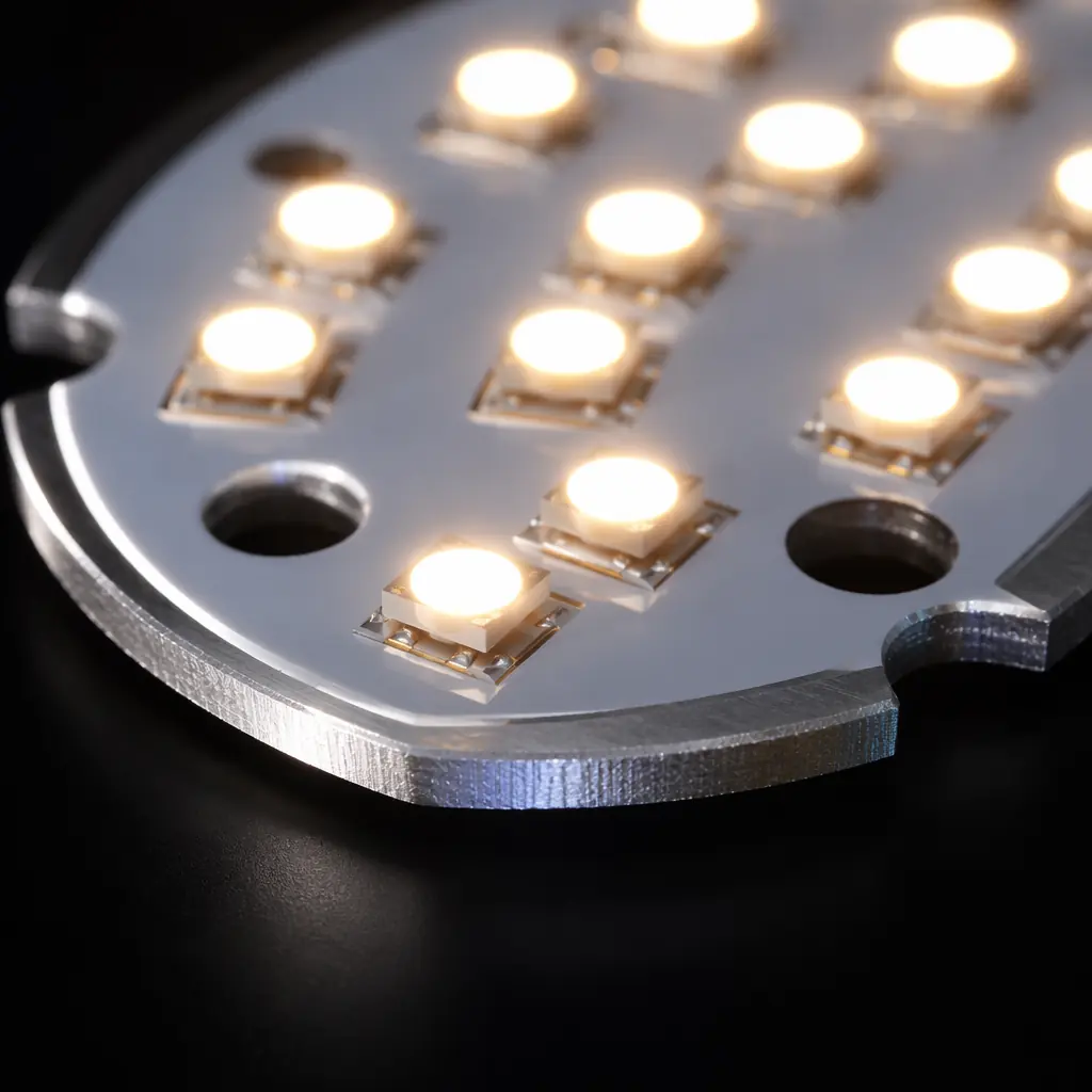
A standard FR-4 board moves heat poorly. It has no continuous metal plane behind the copper, its thermal conductivity is roughly 0.3 W/m·K — a fraction of a percent of aluminium's ~200 W/m·K — and the only way to move heat through it is to drill thermal vias and hope the heat finds a path. A metal-core board replaces that with a solid metal substrate bonded to the copper by a thin thermally-conductive dielectric. Heat no longer has to find a path; it has one. This guide is for the engineer and buyer deciding whether an insulated metal substrate (IMS) board is the right choice for an LED, power, or motor-drive product, and how to specify it so the build is straightforward and the data sheet behaviour is real. It builds on the broader PCB thermal management principles.
What a Metal-Core PCB Is Built From
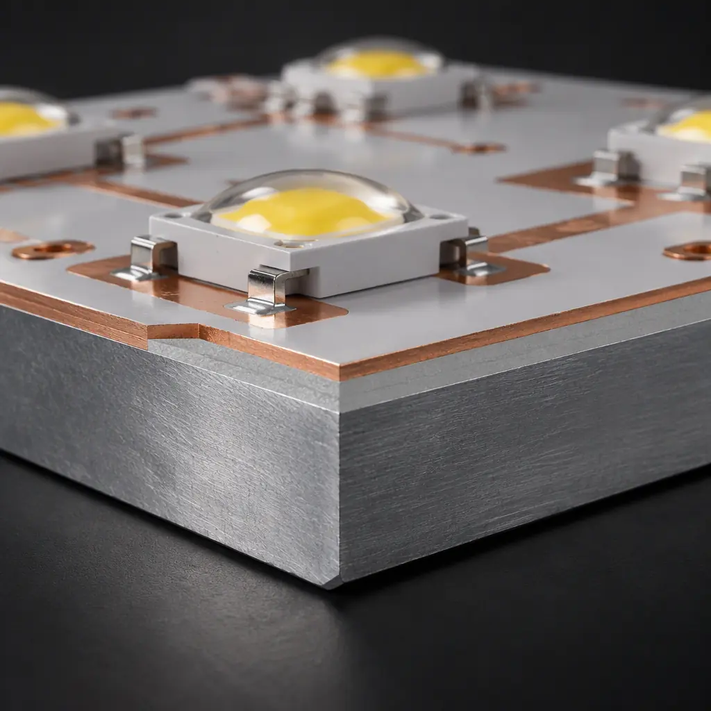
An IMS board is a lamination of three functional layers, and the choice in each matters:
- Base metal. Aluminium is the default — light, cheap, and thermally excellent. Copper is used where thermal performance must be maximised or where the base must be soldered or brazed, but it is heavier and more expensive. Steel appears in some automotive and appliance designs for its mechanical stiffness.
- Dielectric layer. The heart of the construction. A thin thermally-conductive dielectric (often a filled epoxy or polyimide) bonds the copper to the base and provides electrical isolation. Its thickness — commonly 50–150 µm — is the dominant thermal resistance in the stack, and its breakdown voltage rating sets how high-voltage the board can be. Thinner dielectric means better heat transfer but lower isolation voltage, so this is the key design trade.
- Copper circuit layer. Usually 1–4 oz, heavier than typical FR-4 where current is high. Made by etching a standard copper foil bonded to the dielectric.
The dielectric is where quality varies most between suppliers. A cheap IMS board uses a dielectric with poor thermal conductivity and a low breakdown voltage, and the resulting board runs hot and fails a hipot test. Anti-tracking and high-voltage LED drivers in particular need the dielectric rated for the working voltage with margin, and the reliability data behind that rating is worth asking for.
The Single-Sided Limit — the Trap That Catches Designers
The most important limitation of a metal-core board is that, in the classic construction, it is a single-layer circuit. The metal base is a conductor, so you cannot route signal traces on the back the way you would on the second side of an FR-4 board — the whole back is one electrical node (the heat spreader). Everything that connects must be routed on the one copper layer, and any circuit that needs two signal layers must either move to a different construction or be redesigned.
There are workarounds, and it is important to know them at specification time:
- Multilayer IMS. Additional FR-4 layers can be laminated on top of the IMS core, giving you a two- or four-layer circuit while keeping the metal base as the heat spreader. This is more expensive and thicker, but it is the standard solution for power boards that need control logic as well as power.
- Bridged and bonded constructions. Some designs bond an FR-4 portion to the metal base, allowing multi-layer routing in one region and direct metal-core cooling in another.
- Single-layer design discipline. Where the circuit is genuinely simple — an LED array, a motor-driver power stage — a well-planned single layer with an insulating dielectric is entirely adequate and the cheapest option.
Specifying a metal-core board for a two-layer circuit without checking this constraint is the most common and most expensive IMS mistake. The board comes back unbuildable, or it comes back as a multilayer IMS that costs several times what was quoted.
Is a Metal Core Even Needed? Working Through the Alternatives
Before committing to IMS, measure the actual power density. FR-4 handles surprising amounts of heat when it is designed for it, and the cheaper answers should be ruled out first:
| Approach | Cooling Mechanism | Best When | Relative Cost |
|---|---|---|---|
| FR-4 + copper pours | Lateral spreading, convection | Low power density, air flow available | 1.0× |
| FR-4 + thermal vias | Vertical path to back-side plane | Moderate power, small hot spots, BGA-like parts | 1.3–1.8× |
| FR-4 + heat sink / gap pad | Conduction to a bonded sink | High power, mechanical space for a sink | 1.5–2.5× |
| Single-layer IMS | Whole-board metal spreader | High power density, single-layer circuit, no sink space | 2–3× |
| Multilayer IMS | Metal spreader + multilayer circuit | Power + control logic on one board, high power | 3–5× |
The right-hand column is not a hard rule but a guide to the decision: each step up should be justified by a power density that the step below cannot handle. Thermal vias, in particular, are often enough — the thermal interface material and via design determine how much heat they actually move. A metal core earns its cost when the heat per unit area is high enough that spreading it laterally through FR-4 would need an impractically thick copper plane or an unacceptably large board.
Design Rules for the Metal-Core Layer
Once the decision is IMS, a handful of design rules keep the board buildable and reliable:
- Keep copper-to-edge clearance generous. The metal base is exposed at the board edge, and a copper trace running too close can bridge or track across at high voltage. A clearance of at least 0.5 mm from the edge, and more for high-voltage designs, is standard.
- Use thermal-relief or solid connection to the dielectric, not just pads. Components that dissipate heat should sit over a solid copper area on the circuit layer directly above the metal base — the copper area is the heat inlet to the stack. Isolated small pads with thin traces waste the whole point of the metal core.
- Specify the dielectric for the working voltage. A high-voltage LED driver or motor phase needs a dielectric rated well above the peak working voltage, accounting for transients. The breakdown rating is a property of the dielectric material, so this is a material choice, not a layout one.
- Design for the single layer in the layout from the start. If the circuit needs two layers, choose multilayer IMS at specification time rather than trying to squeeze it onto one layer and discovering it cannot be routed.
Where Metal-Core Boards Earn Their Cost
The applications where IMS is the natural answer are consistent, because they share the same shape of problem — high heat per unit area, and little room or budget for a separate heat sink:
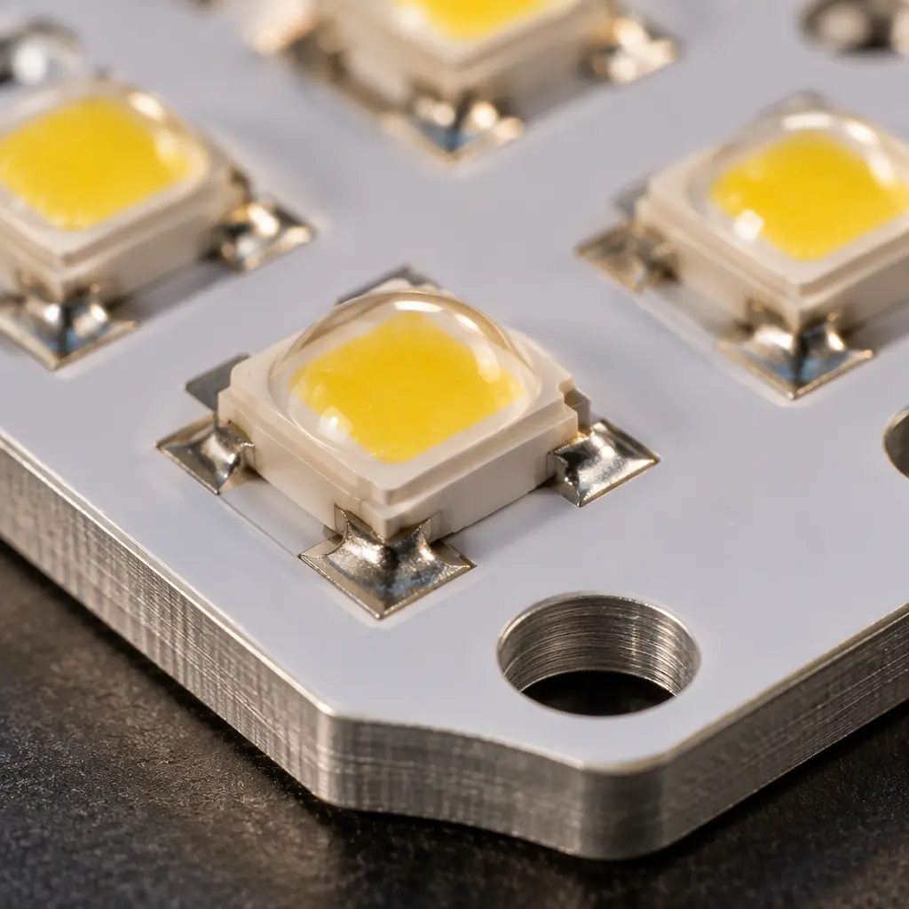
- LED lighting. High-power LED arrays, street lights, automotive headlamps and horticultural lighting all put a lot of heat into a small area, and the metal core is both the heat spreader and often the mechanical structure. See the LED driver systems guide for the driver-side design.
- Power electronics. Motor drives, DC-DC converters and power modules benefit from the low thermal resistance and heavy copper. The power electronics PCB overview covers the broader design context.
- Automotive and appliance power stages. Where the board is bolted to a chassis or housing that becomes the final heat sink, the aluminium base is the interface — which is why the automotive sector (covered in the automotive PCB requirements guide) is a large IMS user.
At Huaxing PCBA, single-layer and multilayer aluminium and copper metal-core boards are fabricated and assembled in Shenzhen, with dielectric options selected for the voltage and thermal requirement of the application. We build to IPC-6012 Class 2 and 3 and assemble LED and power components across the 8 SMT lines. Send your layer stack and thermal requirement for a metal-core quote or talk to an engineer about whether IMS is the right construction for your board.
