

A bridging complaint almost never arrives with the information needed to act on it. It arrives as a photograph of a bridged joint, or a defect count, or a line item in an inspection report. What it does not arrive with is the one fact that determines the correction: whether the bridge existed on the paste before the panel entered the oven.
That single fact splits bridging into two problems that share a word and almost nothing else. Paste-level bridging is a print defect with a print cause and a print fix. Reflow-level bridging is a thermal, material or mechanical problem where the print was correct and the solder moved afterwards. Applying the correction for one to the other is the most common reason a bridging issue survives three rounds of process adjustment.
The Triage: Did the Bridge Exist at SPI
The separation takes one query against data that already exists. Every panel that runs SPI has a record of deposit volume and area for every pad. If adjacent pads had merged paste, the area reading shows it, because a merged deposit is measured as one region rather than two.
| Observation | What It Means | Who Owns It | First Move |
|---|---|---|---|
| Merged deposits visible at SPI, before reflow | Paste touching at print | Print process / stencil | Aperture area, then pressure |
| Distinct deposits at SPI, bridged after reflow | Paste moved during heating | Reflow profile / material | Soak and ramp rate first |
| Distinct deposits at SPI, high volume | Clean print but excess paste per pad | Stencil geometry | Aperture reduction |
| Bridge on one component, random across panel | Placement offset or coplanarity | Placement | Placement accuracy on that part |
| Bridge repeatable at one board position | Local seal or support failure | Printer mechanics | Board support at that position |
Only the first, third and fifth rows are print problems. The second and fourth are not, and no amount of squeegee tuning will fix either. This is why the triage has to precede the adjustment: it is not a formality, it is the fork in the road.
Paste-Level Bridging: The Mask Dam Is the Real Variable
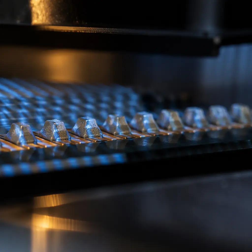
When paste bridges at print, the question is whether a bridge was even preventable at that pitch. Between two adjacent pads there is a strip of solder mask, the dam, and its width sets how much paste can be pushed sideways before the two deposits touch. A dam that is too narrow cannot hold the separation no matter how the printer is set.
| Pitch | Pad Gap | Workable Dam | Practical Consequence |
|---|---|---|---|
| 0.65 mm | ~0.30 mm | 0.125–0.150 mm | Comfortable. Printing is not the constraint. |
| 0.50 mm | ~0.25 mm | ~0.100 mm | Workable. Dam must be defined deliberately, not left to default. |
| 0.40 mm | ~0.20 mm | ~0.075 mm | Marginal. Dam printing becomes the yield limit. |
| 0.30 mm | ~0.15 mm | Below 0.065 mm, not reliable | A printable dam effectively does not exist. |
Below roughly 0.065 mm, the dam stops being a manufacturable feature. Mask at that width does not survive imaging and development reliably, so what arrives on the board is a partial dam, sometimes present and sometimes not, which produces bridging that appears random. When that threshold is crossed the dam is no longer the control, and the aperture has to be reduced so the deposit itself is small enough to stay on its pad.
That is the design answer, and it belongs in the stencil rather than in the printer. Our guide to stencil aperture design and paste release covers how aperture area is reduced at fine pitch while keeping the area ratio high enough to release paste at all, which is the constraint that limits how far the reduction can go.
The Order of Correction: Area Before Pressure
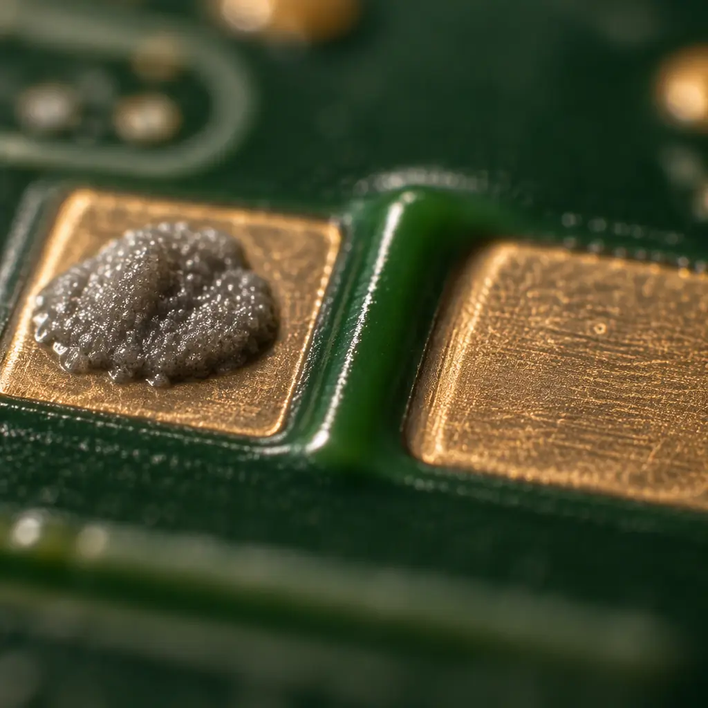
When paste bridging is confirmed and the dam is manufacturable, there are two knobs: aperture area and printer pressure. They have opposite failure modes at the limit, and the order they are tried in determines whether the problem converges or oscillates.
Reduce aperture area first
Reducing aperture width or length reduces the paste volume at its source. The change is stable, it does not interact with the other defects, and it holds across shifts. Typical reductions run from 5 percent on the width to 10 percent on the length, and a reduction that keeps the area ratio above the release threshold costs nothing in another defect class.
Then reduce squeegee pressure, in small steps
Pressure that is too high forces paste under the stencil and out to the sides of the aperture, which is a bridge at print and a bead after reflow. Reducing it is effective but interacts with transfer efficiency: too low and the stencil does not seal, which produces insufficient paste instead. Move in small increments and check both defects after each.
Adjust separation speed last
Faster separation tears deposits and favours bridging; slower separation improves release but lengthens cycle time. It is the last knob because it is the one most likely to convert a bridging problem into insufficient paste, and because it has the least direct effect on the bridge itself when the aperture is oversized.
The oscillation pattern this order prevents is familiar: pressure reduced to stop bridging, insufficient paste appears, pressure raised again, bridging returns. Each adjustment is locally correct and the pair never converges, because the actual constraint was aperture volume the whole time. Working by cause rather than by symptom is the same discipline that applies across the rest of the printing defect set, set out in our solder paste printing defects guide.
Reflow-Level Bridging: When the Print Was Correct
If SPI recorded distinct deposits and the joints are bridged afterwards, the solder moved during heating. Three mechanisms do that, and they are distinguishable by where the bridge sits and what else is wrong on the same panel.
Slump Above the Liquidus
Paste that is at the low end of its viscosity specification can hold shape at room temperature and still collapse once it reaches temperature, before the flux has had time to activate. The bridge appears on the same component class across the panel and is worse on runs where the paste has been open longer. The signature is a deposit that was measured correct at SPI and a joint that bridged anyway, on a paste lot with a long open time. Viscosity behaviour and its temperature dependence are covered in our paste rheology and slump guide.
Ramp Rate Too Aggressive
A fast ramp heats the paste before the flux has driven off the volatiles that keep it coherent. The paste boils and spits rather than melting in place, and the result is a mix of bridges and solder beading on the same panel. Read the profile against the paste datasheet rather than against a generic curve, and check whether the ramp rate changed since the last known-good run.
Component Coplanarity and Placement Offset
A leadless part that sits fractionally low on one side, or a lead that lands half on its pad, produces a bridge on that part alone while the rest of the panel is clean. The tell is distribution: thermal and material causes are diffuse across the panel, mechanical causes are concentrated on one component or one placement location. Check whether the bridged part is the one with the tightest lead pitch, because that is the part that fails first when placement drifts.
What to Record So the Next Complaint Is Answerable
Bridging complaints recur because the evidence that would settle them is not captured at the time. Four values per lot make the triage automatic rather than archaeological.
SPI area reading per pad, not just volume
Volume alone does not show a merge; area does. A merged deposit has an area larger than the aperture, which is the direct evidence that the bridge existed before reflow.
Mask dam width as drawn and as measured
The as-drawn value comes from the Gerber and the as-measured from the first article. The gap between them is where bridge complaints originate, because a dam drawn at 0.08 mm may arrive at 0.05 mm after imaging tolerance.
Reflow profile as run, with the ramp rate at the soak
A profile that was correct when qualified drifts with oven loading and element condition. Recording the rate as run is what allows a sudden bridging onset to be matched to a profile change.
Paste lot, open time, and viscosity if the supplier provides it
Slump-related bridging is a material property, and the only way to make a material claim is to hold the lot identity at the time of the failure. Our paste storage and handling guide covers the working window that keeps viscosity in range.
Where Bridging Sits in the Wider Defect Set
Bridging is one of eight common printing signatures, and it overlaps with insufficient paste more than the usual framing suggests. Both are decided by the transfer step, and both respond to separation speed in opposite directions, which is exactly why a line can oscillate between them. Our diagnosis for insufficient paste works the same arithmetic from the low-volume side.
When the question becomes who owns the bridge rather than how to fix it, the answer needs a numeric gate attached to each defect class, which is the structure described in our solder paste defect attribution method. And when the bridge has already cost a rework batch, our breakdown of what each printing defect costs prices the consequence rather than the cause.
At Huaxing PCBA, SPI captures volume and area per pad on every print, so a bridging complaint can be checked against the paste record rather than inferred from the joint. Mask dam widths are checked against the pitch at design review, and apertures below the printable dam threshold are flagged for reduction before the stencil is cut. Send your Gerber and BOM for a free DFM review and quote.