
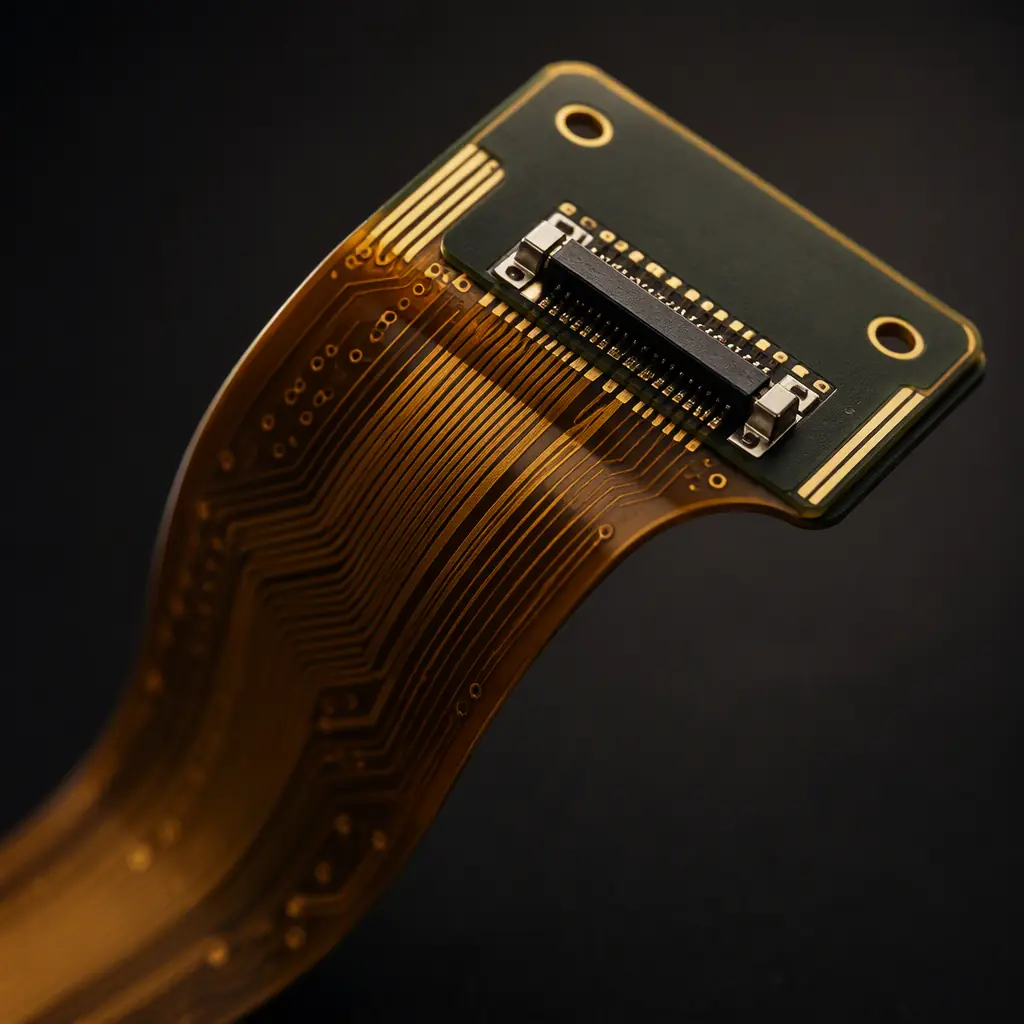
A flex circuit is a brilliant solution right up to the moment you try to plug a connector into it. Polyimide flex bends, and that flexibility is the product's superpower. But the same property makes a bare flex tail useless for a board-to-board connector, a screw mounting point or a component that needs a flat, rigid surface. The stiffener is the answer: a locally bonded rigid layer that turns a specific zone of the flex into a stable mounting platform while the rest of the circuit keeps bending.
Stiffeners are one of the most common sources of flex-board rework and field failure, yet they are usually specified with a single line on the drawing, "add stiffener here", with no material, thickness or tolerance. This guide covers the decisions that actually matter: which material, how thick, where it goes, how it is bonded, and what to verify before the board ships. Huaxing PCBA manufactures flex and rigid-flex boards with stiffener lamination as a standard capability, and this is the same guidance our DFM engineers apply to every flex order.
What a Stiffener Does, and Does Not Do
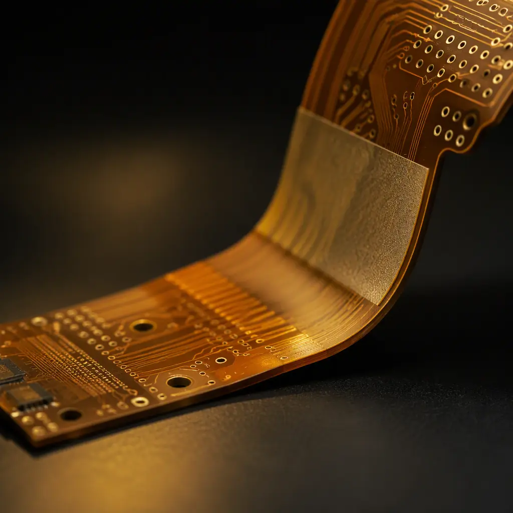
A stiffener adds local rigidity to a flex circuit without adding rigidity to the whole board. It is not an alternative to choosing a rigid-flex design, it is a targeted fix for specific zones.
| Stiffener Job | Typical Location | Common Material |
|---|---|---|
| Connector mounting | FFC/FPC tail, board-to-board zones | FR-4 or polyimide |
| Screw / standoff mounting | Holes, mounting pads | FR-4, steel, aluminum |
| Component support | BGA, connector, heavy parts | FR-4 or polyimide |
| Handling / assembly aid | Panel edges, test points | Polyimide |
| Ground plane / shield | EMI zones | Steel, aluminum |
The stiffener does not need to cover the whole flex, in fact it should not. Covering a bend zone with a stiffener defeats the purpose of the flex and adds stress concentration at the stiffener edge, which is exactly where cracks start. The design intent is always: stiffen the zone, leave the bend free. Our flex PCB design and manufacturing guide covers the base design rules this builds on.
Stiffener Materials: FR-4 vs Polyimide vs Metal
The three material families differ in stiffness, thickness range, cost and how they bond to the flex. The choice follows the mechanical job, not habit.
FR-4 stiffener, the workhorse
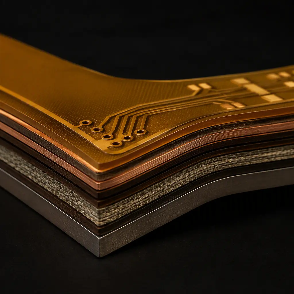
FR-4 is the default for connector zones and mounting pads. It comes in standard PCB thicknesses (0.4–1.6 mm), bonds with adhesive, and matches the thermal behaviour of the flex during assembly. It is cheap, flat and dimensionally stable. The main constraint is thickness: a 1.6 mm FR-4 stiffener on a 0.1 mm flex creates a large step at the transition, which stresses the flex edge and complicates pick-and-place. Most connector stiffeners land at 0.2–0.5 mm for FFC tails and 0.8–1.6 mm where a component sits on top. Material behaviour parallels what our PCB materials guide documents for rigid boards.
Polyimide stiffener, thin and flexible-tolerant
Polyimide stiffeners (typically 0.05–0.15 mm) are used when the stiffened zone must stay very thin. For FPC connectors in tight enclosures, or where the board must conform to a shallow curve after assembly. They add rigidity but less of it than FR-4; a polyimide stiffener mostly prevents curl and provides a flat surface rather than true structural support. They are also the natural choice when the stiffener must survive the same bending environment as the rest of the flex.
Stainless steel and aluminum, structural and shielding
Metal stiffeners are the choice for load-bearing mounting (screw bosses, chassis mounting) and for EMI shielding zones. Steel at 0.1–0.3 mm gives the highest stiffness-to-thickness ratio, and a metal stiffener can double as a ground plane, useful in the antenna and high-frequency flex designs covered in our PCB antenna design guide. The trade-offs are weight, cost and the bonding process: metal needs a compatible adhesive system and surface prep to avoid delamination under thermal cycling.
Key Takeaway: There is no "best" stiffener material, there is a right material for each zone. Ask three questions per zone: how much load, how thin must the stack stay, and does the zone also need shielding? The answers pick the material; the drawing then just documents it.
Thickness and Placement Rules
Stiffener thickness and position are where most flex designs go wrong. The rules below are the ones our DFM review checks first on every flex order.
Keep the stiffener edge off the bend line
The stiffener edge is a stress concentration point. The transition from stiffened to flexible zone must sit outside the bend radius, with a clearance of at least 2–3× the flex thickness from the bend line, more for dynamic-flex applications. If the stiffener ends exactly at the bend, the flex cracks at the edge within thousands of cycles. Bend radius and dynamic-flex rules are detailed in our flex PCB guide.
Match thickness to the connector spec
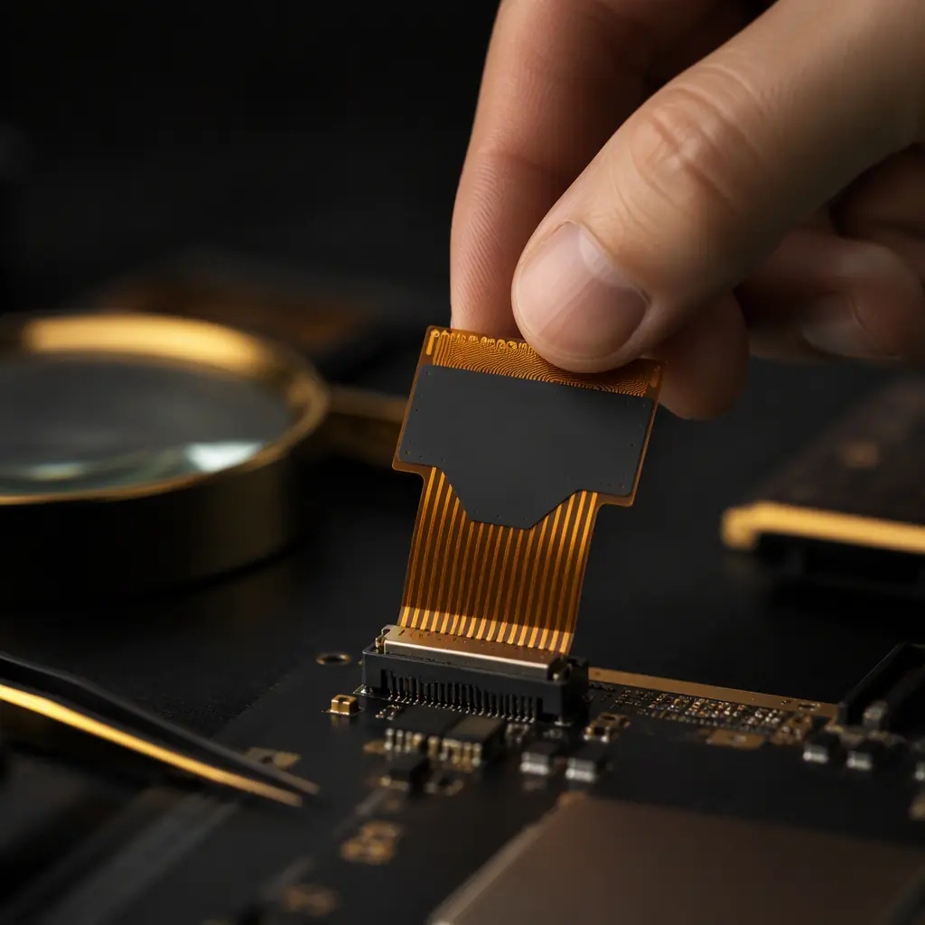
FFC/FPC connectors are spec'd for a total tail thickness: typically 0.3 ±0.03 mm for 0.5 mm pitch and 0.2 ±0.02 mm for 0.3 mm pitch. The stiffener plus flex plus adhesive must land inside that window. This is the single most common stiffener error: a 0.2 mm stiffener on a 0.12 mm flex exceeds the connector's 0.3 mm limit and the tail does not seat. Verify the total stack against the connector datasheet before fabrication.
Cover the full connector or mounting footprint
The stiffener should extend a few millimetres beyond the connector body or screw pad on every side so the load spreads into the flex, not onto its edge. For screw mounting, the stiffener must carry the hole and a 3–5 mm border of bonded area around it; a stiffener that stops flush at the hole edge delaminates under torque.
Consider the assembly side
Stiffeners can be bonded to either side of the flex, but the side matters for assembly: a stiffener under a component zone on the SMT side interferes with placement, while a stiffener on the opposite side supports the component. For double-sided stiffened designs, coordinate both in the stackup. The panelization and nesting implications are covered in our panelization guide.
Bonding Methods: Adhesive, PSA and Lamination
How the stiffener attaches is as important as what it is made of. The three main methods differ in bond strength, temperature tolerance and reworkability.
| Method | Bond Strength | Temp Tolerance | Best For |
|---|---|---|---|
| Thermal-set adhesive (prepreg) | High | Up to reflow | FR-4 stiffeners, permanent joints |
| PSA (pressure-sensitive adhesive) | Medium | Limited (softens with heat) | Polyimide stiffeners, quick builds |
| Co-lamination | Highest | Full process | Metal stiffeners, rigid-flex zones |
Thermal-set adhesive is the default for FR-4 stiffeners: the adhesive film is laminated under heat and pressure, producing a permanent bond that survives reflow. PSA is faster and cheaper but softens at soldering temperatures, so it suits stiffeners that never pass through reflow, handling aids and test zones. Metal stiffeners are usually co-laminated with the flex layup itself, which gives the strongest bond but locks the stiffener position at the panel stage. Bonding defects, edge voids, adhesive squeeze-out into the bend zone, are exactly what a good DFM review and first article inspection catch; see our first article inspection guide for the verification steps.
DFM Tip: Specify the bonding method on the drawing, not just the material. "FR-4 stiffener, 0.3 mm, thermal-set adhesive" is a manufacturable instruction. "Add stiffener" is a gamble.
Stiffeners in Rigid-Flex: The Overlap to Understand
Stiffeners and rigid-flex are sometimes confused, and the distinction matters for cost and reliability. A rigid-flex board is manufactured as one part: the rigid zones are real multilayer rigid PCB sections, and the flex zones are the exposed flex between them. A stiffener, by contrast, is a separate layer bonded onto a flex circuit. It does not carry etched copper and is not part of the electrical design.
The practical question is when to use which. If the rigid zone needs multiple copper layers, plated holes and components, that is a rigid-flex requirement, see our rigid-flex PCB guide for the design rules. If the zone only needs a flat surface for a connector or a screw, a stiffener on a plain flex is far cheaper and faster to iterate. Many products use both: a rigid-flex spine for the electronics and stiffeners at the tail connectors.
Verification and Common Failure Modes
Stiffener defects rarely show up at electrical test, the board works, then fails mechanically in the field or during assembly. The failure modes to design out and inspect for:
Delamination at the stiffener edge
Edges lift when the bond area is too small, the adhesive is under-cured, or the edge sits in a bending zone. Prevention: adequate border around the functional area, correct adhesive cure, and a transition clearance from any bend. Thermal cycling testing, see our thermal cycling guide . Exposes weak bonds before shipment.
Tail thickness out of connector spec
Measured with a micrometer at incoming inspection: if the stiffened tail exceeds the connector's thickness window, the connector cannot seat and the board is scrap. Verify total stack on the first article and per lot.
Adhesive bleed and contamination
Squeeze-out from the stiffener edge can contaminate pads or the bend zone. This matters most for cleanliness-sensitive designs, the ionic contamination checks in our cleanliness guide apply here too. Visual inspection of the stiffener perimeter catches bleed early.
Summary: The Stiffener Specification Checklist
For every stiffened zone, specify five things: material (FR-4, polyimide or metal), thickness (tuned to connector spec and load), position (clear of bend lines, covering the full footprint), bonding method (thermal-set adhesive, PSA or co-lamination) and assembly side. Verify the total stack against the connector datasheet, confirm the transition clearance on the drawing, and inspect the first article for delamination and bleed. Done this way, a stiffener is a cheap insurance policy; done casually, it is a rework ticket.
At Huaxing PCBA, we manufacture flex and rigid-flex boards with FR-4, polyimide and metal stiffeners laminated to tolerance, across our standard and quick-turn lines. Read our panel utilization guide to see how stiffened flex panels are optimised for cost, or send our engineering team your flex design for a free DFM review of the stiffener zones within 24 hours.
