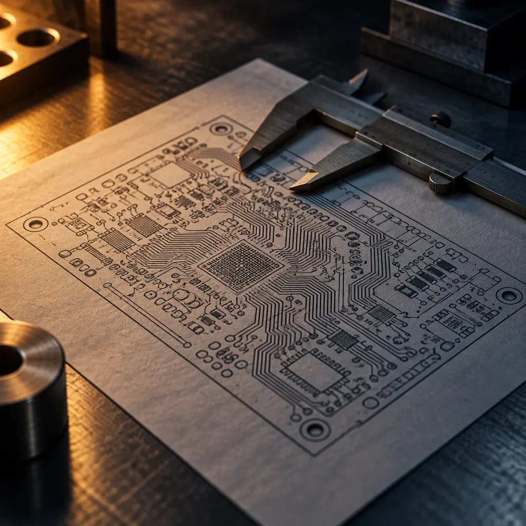
A callout of ±0.075 mm on a finished hole, copied from a template drawing, will add between 15 and 40 percent to a two-layer prototype order and nobody will tell you why the number moved. The fabricator priced it, the buyer accepted it, and both parties move on with a wrong assumption about what that tolerance buys. This page is about what each tight callout costs at the drill, the etcher and the plating line, and which ones a purchasing team can loosen without touching function.
The pattern is consistent across quotation files. Of the RFQs we receive where a customer has stated tolerances explicitly, roughly one in eight states something tighter than the process the design actually requires, and in almost every case the tightest callout is on a dimension that is not functional. The functional dimensions are usually ignored, because nobody flagged them. A drawing is not a specification of intent; it is a list of numbers, and numbers cost money in direct proportion to how close to the process limit they sit.

Which Callouts Actually Drive the Price
Four numbers on a drawing dominate fabrication cost. Everything else is either free or already included in the process capability. The four are finished hole diameter, annular ring, layer-to-layer registration on multilayer builds, and trace width on outer layers. A fifth, impedance, behaves differently because it is measured on a coupon rather than on the board and is therefore negotiated against a statistical process rather than a single measurement.
| Callout | Common drawing value | Process capability (no premium) | Effect of tightening |
|---|---|---|---|
| Finished hole diameter | ±0.075 mm | ±0.10 mm (≤0.30 mm drill), ±0.125 mm above | Drill reamers, slower feed, 100% pin gauge, adds 1 day and 8-20% on drilling |
| Annular ring (minimum) | 0.05 mm | 0.075 mm on Class 2, 0.10 mm typical on 1.6 mm builds | Registration control tightened, inner-layer lamination re-checked, scrap rate up 2-5 points |
| Layer registration | ±0.05 mm | ±0.075 mm (≤8 layers), ±0.10 mm above | Tooling holes reamed, X-ray on every panel, adds 0.5 day per lamination cycle |
| Outer trace width | ±10% | ±20% on 1 oz, ±15% on 0.5 oz | Etch compensation per panel, AOI first-article on every lot, 5-12% on the fab price |
| Board thickness | ±10% | ±10% (standard), ±7% on ≤8 layers | Press cycle monitored per book, platen shimming, 3-8% premium |
The surprise for most buyers is the first row. Hole tolerance sounds like a machining precision claim, but on a drilled board it is really a statement about how the hole is finished. A ±0.10 mm window accommodates drill wear across the panel and the plating thickness variation that follows it. A ±0.075 mm window forces the shop to ream after plating and to gauge 100 percent of holes rather than sample them, because a single worn drill in a 3000-hit stack can put a whole lot outside the band. On a part where the hole receives a press-fit pin, that tolerance is functional and worth buying. On a part where the hole takes a through-hole resistor lead, it is decoration.
Finished Hole vs Drill Size — the Arithmetic Buyers Get Wrong
The drawing specifies a finished hole, but the drill is chosen smaller to leave plating thickness. On a standard 25 µm copper and 8 µm tin-lead or ENIG deposit, the finished diameter is roughly the drill diameter minus twice the plating thickness, and that subtraction is where the tolerance band collapses.
Take a 0.90 mm finished hole with a ±0.075 mm callout. The plating thickness is itself specified at ±8 µm, and copper thickness varies from panel centre to panel edge by a few microns on a high-aspect-ratio hole. The drill must therefore be selected such that drill size minus two plating thicknesses lands inside 0.825 to 0.975 mm for every hole in the panel, not just the average. Shops that keep a drill log will tell you the practical drill window for that part is ±0.04 mm, which is tighter than the drill tolerance itself on a standard carbide bit over a 3000-hit life.
The consequence is not a rejected lot as often as it is a quotation the buyer cannot compare. One shop prices 100 percent pin gauge inspection, another prices reaming, and a third quotes the loose tolerance and later refuses the first article. We have seen three quotes on the same file differ by 38 percent on the fabrication line alone purely from reading the ±0.075 mm callout differently. For press-fit and connector pins the callout is real and needs to bind; for everything else, the finished hole tolerance belongs at ±0.10 mm and the money is better spent on press-fit retention control where it actually influences assembly yield.
Impedance: Measured on a Coupon, Not on Your Board
An impedance callout of ±10 percent is common and ±5 percent appears on high-speed designs. Neither is measured on the boards you receive. Impedance is verified on a test coupon built onto the production panel with the same stackup, and the coupon is measured by TDR. The number the supplier reports is a coupon statistic, which means the cost of a tighter callout is not a slower process but a wider coupon and a tighter statistical window on a measurement the board never sees directly.
The practical effect is that a ±5 percent impedance callout is often achievable without process change, provided the stackup allows it. It is the stackup, not the tolerance, that decides. If the design has a thin dielectric with a wide trace, the etch tolerance dominates the impedance variance, and no amount of care on the press will recover it. If the design has a well-conditioned geometry, ±5 percent falls out of normal control. Our impedance control and hybrid RF stackup pages cover the geometry side, and TDR coupon measurement covers how the acceptance number is produced. When a customer tightens impedance without changing stackup, we quote the premium and flag it, because the tolerance alone rarely buys the result they want.

Cutting the Cost Without Touching Function
The useful exercise before an RFQ is not deciding which tolerances are tight, but deciding which dimensions are functional and which were inherited. A functional dimension is one where a mating part, a press-fit pin, an optical element or an RF launch defines what is acceptable. Those should be called out explicitly and individually. Everything else should be governed by a general tolerance block, which most fabricators apply at no premium.
Three changes recover most of the avoidable cost on a typical file:
First, replace the finished hole tolerance with a note that distinguishes plated through-holes used for mating hardware from via and lead holes. A single ±0.10 mm general callout plus one ±0.05 mm callout on the four connector pins will cost less than a blanket ±0.075 mm and will protect exactly the dimensions that matter.
Second, move the annular ring requirement to the IPC class instead of a number. IPC-6012 Class 2 permits a smaller minimum annular ring than most drawings state, and Class 3 is required only for specific applications. A drawing that calls 0.05 mm minimum on a Class 2 build is not requesting a better board, it is requesting an inspection argument. The IPC Class 2 vs Class 3 comparison shows where the two diverge in a way that affects yield.
Third, for multilayer builds above eight layers, stop specifying layer registration as a single number and specify it as a measured value with a coupon. Registration on a 12-layer book is dominated by lamination movement, and a supplier that reports the measured registration on a per-book basis will control it better than a supplier chasing a drawing number that has no measurement path attached.
The same logic applies to the broader cost structure of a quote. The line-by-line quote breakdown shows which line items these tolerance decisions land in, and PCB manufacturing tolerances gives the standard capability table per feature. Reading those two before rewriting a drawing typically removes more cost than any negotiation on unit price.

What to Ask For in the Quote
A quotation that responds to a tight tolerance without explaining it is not a controlled quotation. Ask for two numbers on each tight callout: the process capability the shop will run, and the inspection method that proves it. If the method is sample-based and the tolerance is tighter than three sigma of the process, the tolerance is not being held, it is being hoped for.
We return both, plus the specific callouts we think are counterproductive on the drawing, in the DFM review attached to every quote. That review is free and it is the cheapest place to find out that a ±0.075 mm callout on a lead hole has been costing you money on every order since 2019.
Summary
Tolerances cost money in proportion to how close they sit to the process limit, and the four callouts that dominate fabrication cost are finished hole diameter, annular ring, layer registration and outer trace width. Impedance is a coupon statistic and behaves differently. Call out the functional dimensions individually, govern the rest with a general block, reference the IPC class instead of writing a number, and ask each supplier to state both capability and inspection method for anything tight. On a typical file that removes tens of percent of the fabrication price without changing a single functional requirement.