A press-fit joint is made by forcing a compliant pin into a plated hole that is smaller than the pin's widest section. The pin deforms elastically, the hole walls take the reaction, and the resulting interference is what holds the connector in place and what makes the electrical contact. Almost every press-fit conversation a PCB buyer has with a fabricator is about insertion force, because insertion force is what the press records and what the operator signs off. Retention force is the number that matters after the product ships, and it is measured by a completely different test that most orders never specify.
The gap between the two is where the expensive failures live. A joint can insert comfortably inside its window and still release under vibration, because insertion force is dominated by the entry geometry of the hole and retention is dominated by the sustained interference further down the barrel. This page separates the two measurements, sets out what actually determines retention, gives the numbers by pin size, and describes the failure modes that pass an insertion check without difficulty.
Two Forces, One Joint
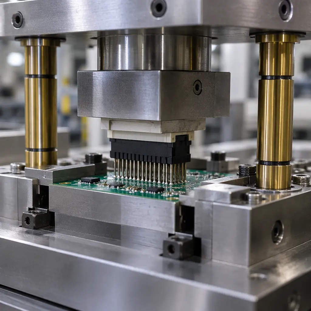
Insertion force is the peak force needed to get the pin past its widest point. It is a single number, it is measured on the press in newtons per pin or per connector, and it is useful as a process control: too low means the hole is oversized or the plating is thin, too high means the hole is undersized or the pin is entering at an angle and the connector will crack the barrel. For a board fabricator, insertion force is the proxy for hole diameter that arrives without the customer needing to measure anything.
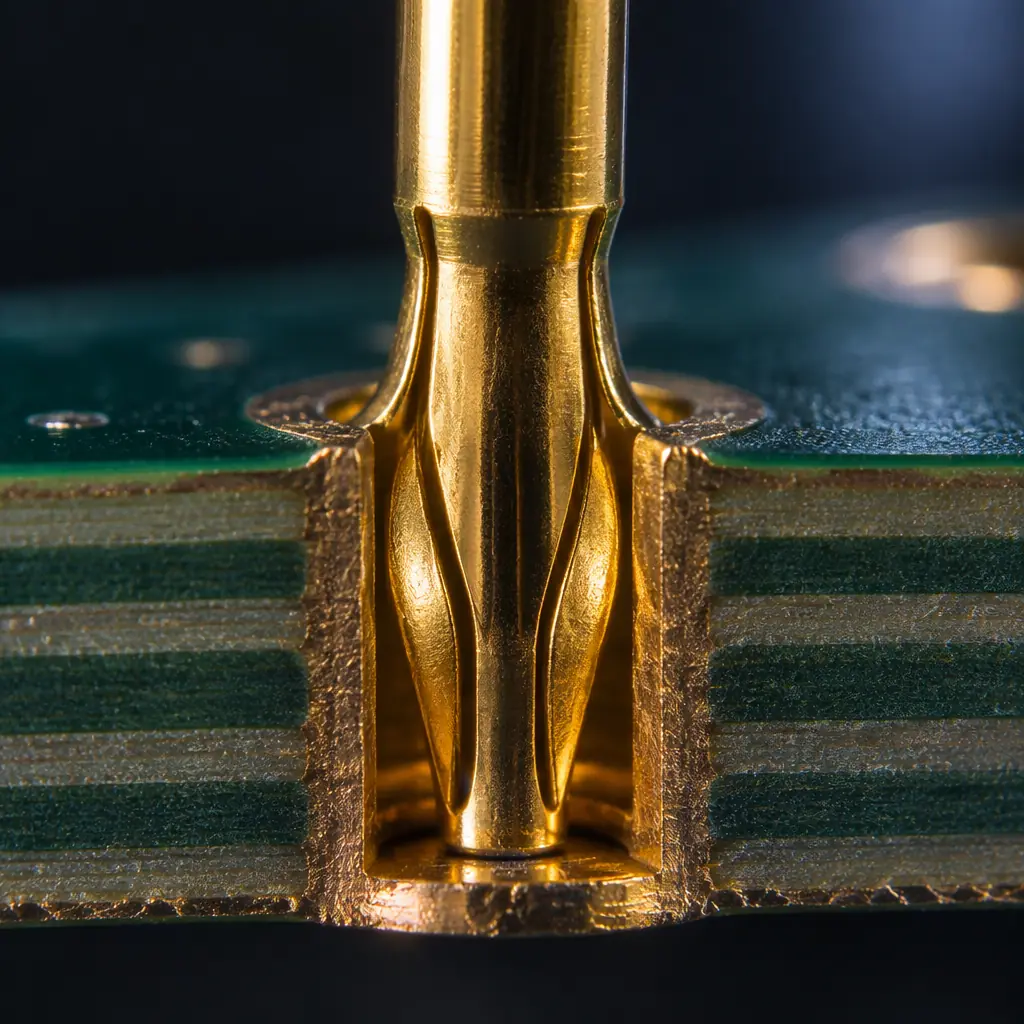
The eye of the needle is the compliant section. Its spring action sets the interference, and the interference sets both forces.
Retention force, sometimes called pull-out or push-out force, is the force needed to remove the pin after it is seated. It is measured by gripping the pin, or the connector housing, and pulling at a controlled rate until the joint releases. It is a different number from insertion force, it is measured on a sample rather than on every board, and it is the number that answers the question the customer actually asked: will this joint stay together.
A properly formed eye-of-needle joint typically shows a retention force lower than its insertion force, which surprises people who expect the two to match. The reason is that insertion has to overcome the full elastic compression of the eye plus friction over the whole insertion length, while retention only has to overcome the residual interference after the pin has settled. A joint with 30 newtons of insertion and 15 newtons of retention is healthy. The same connector reading 30 newtons of insertion and 6 newtons of retention is a hole problem, even though the press log looks identical.
What Sets Retention
Five variables decide how much force a joint will hold, and only one of them is controlled by the fabricator. The others are set by the design and by the connector the buyer chose, which is why retention problems are usually diagnosed after the fact rather than prevented at the quote.
Hole diameter is the dominant variable. Retention falls steeply as the hole grows, and the fall is not linear: a hole at the top of its tolerance band can lose a third of its retention compared with nominal, because the eye is already partially collapsed before the pin seats. This is the reason hole tolerance on a press-fit drawing is tighter than on a general-purpose board, and why the tolerance belongs in the purchase order rather than in a general note.
Plating thickness and ductility come second. A hole plated to 25 microns of copper holds better than one plated to 20 microns, and a hole with a brittle or poorly bonded plating fails differently: instead of the pin relaxing, the plating cracks and the interference disappears entirely. Thin plating also reduces the barrel's ability to resist the radial load without barrel distortion, which shows up as a retention number that scatters between pins on the same connector.
Pin geometry is the third. Eye width, eye length and the relief geometry determine how much spring the pin can deliver before it yields. A pin designed for a 1.0 mm hole will not deliver proper retention in a 1.05 mm hole no matter what the drawing says, and pushing it there produces a joint that passes insertion and fails pull-out. The connector maker's application specification states the intended hole range, and it is the only authority on it.
Board thickness matters because retention is force per unit of engagement. A 1.6 mm board gives a pin more barrel to grip than a 1.0 mm board, and thin boards need either a longer pin or a lower retention expectation. Finally, reflow exposure before pressing changes retention: a board that has been through reflow has been through thermal expansion and its plating has been annealed, and the resulting joint is slightly more compliant than one pressed into a bare board. The direction of the effect depends on the plating chemistry, which is why press-fit assembly process treats press-before-reflow and press-after-reflow as different processes rather than as a scheduling preference.
The Numbers
The table below gives typical retention per pin for common press-fit pin sizes. The ranges are what we observe on compliant pins pressed into correctly plated holes at the low end of the hole tolerance band, and they are for orientation, not for acceptance. Acceptance comes from the connector maker's application specification and from the retention test the purchase order defines.
| Pin section | Hole diameter | Typical retention per pin | Typical insertion per pin | Notes |
|---|---|---|---|---|
| 0.5 mm square, short eye | 0.60 mm | 8 to 14 N | 18 to 25 N | Dense backplane, thin boards need a length check |
| 0.6 mm square | 0.75 mm | 12 to 20 N | 25 to 40 N | General signal connectors |
| 0.8 mm square | 1.00 mm | 20 to 35 N | 40 to 70 N | Power and mixed-signal headers |
| 1.0 mm square | 1.15 mm | 35 to 55 N | 60 to 100 N | High-current, needs a press capacity check |
| Compliant pin, 1.2 mm nominal | 1.35 mm | 45 to 70 N | 80 to 130 N | Board support and heavy connectors |
The per-pin figures are the useful unit, because the connector-level number is simply the sum across the pins that share the load, multiplied by a derating factor. A 60-pin connector at 20 newtons per pin does not hold 1,200 newtons: the load is never perfectly shared, and the pins that seat first carry less than the pins that seat last. For connector-level specification, treat the per-pin figure as an average and require the connector maker's stated minimum total, which accounts for the distribution.
Retention also has to be read against what the joint will see. A board in a static indoor enclosure with no cable strain can live with the bottom of the range. A board with a cable harness hanging off the connector, or one that sees vibration from a motor or a vehicle, needs the top of the range plus a mechanical anchor, and at that point the retention force is a secondary defence rather than the primary one.
How Retention Is Measured
A retention number without a test method is not a specification. The three parameters that make it meaningful are the pull rate, the sample size and the point at which the joint counts as failed.
The pull rate should be slow and controlled, typically a few millimetres per minute, because a fast pull measures the peak dynamic response rather than the static holding force and will read high. The sample should be a stated number of pins across at least three connectors from different positions on the panel, because the process variation that matters is between holes, not between boards. The failure criterion should distinguish the modes: pin pull-out from the hole, pin breakage, connector housing separation and pad lift are four different results, and only the first is a retention failure.
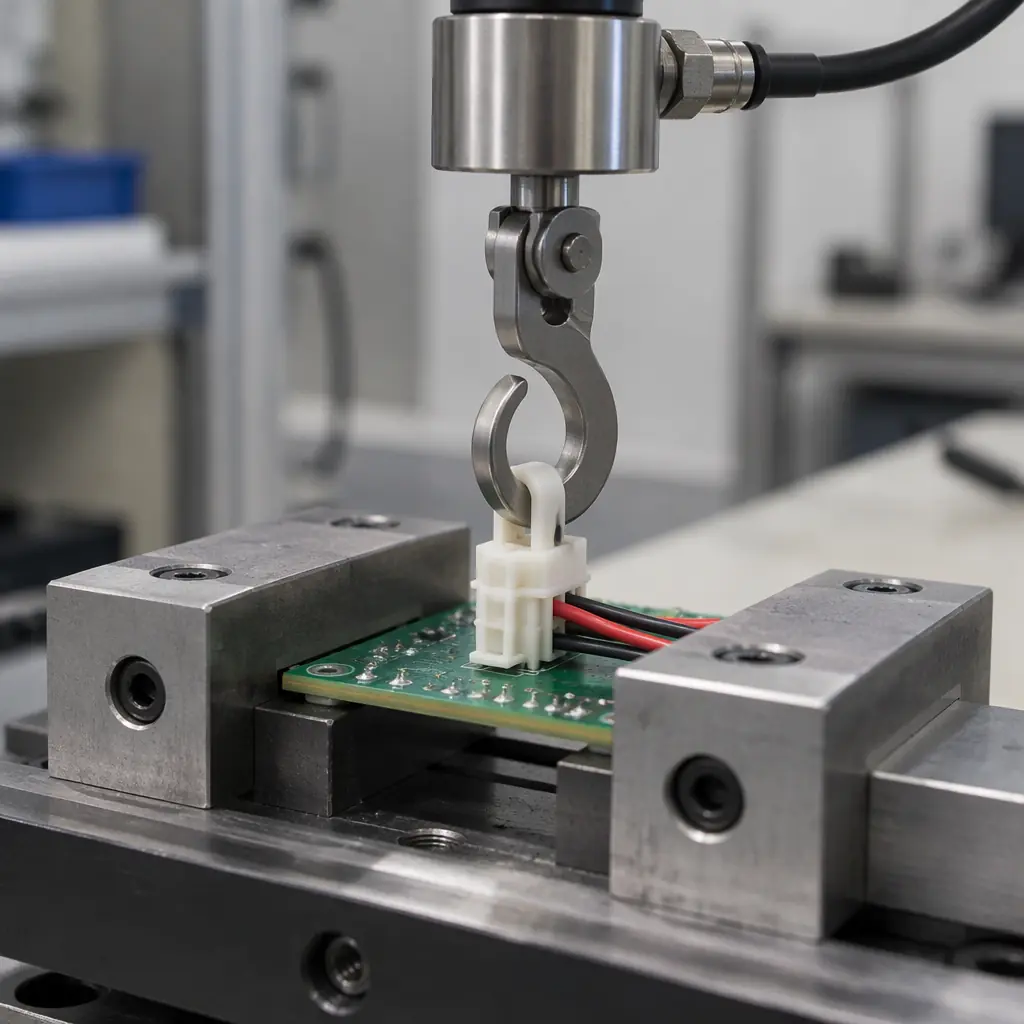
Retention is a destructive test on a sample. The number is only comparable when the rate, the sample and the failure mode are all stated.
The most useful place to run it is first article, on the same panel position as the production connector, paired with a microsection of a pressed hole from the same lot. The cross-section report shows whether the plating deformed the way the pin design expects; the pull test shows what the deformation is worth. Neither number alone tells you whether the process is in control.
Periodic retention testing during production is worth specifying only where the connector is mechanically critical. For a backplane header in a rack, the annual cost of a pull test on three connectors per lot is trivial against a field failure, and the test doubles as an early warning on plating thickness drift. For a board-to-board connector inside a sealed enclosure, the test is mostly documentation, and the same money is better spent on hole diameter control.
The Failures Insertion Force Cannot See
Four failure modes produce a joint that presses normally and holds badly. Knowing them is what converts a retention specification from a number into a process.
The first is an oversized hole at the top of tolerance. The pin presses easily, the press log looks excellent, and the eye never fully collapses, so the residual interference is a fraction of design intent. The signature is low retention with low insertion, and the cause is a drill that is running at the high end of its band or a plating that is at the thin end of its range on the same hole.
The second is plating cracking during press. The pin expands the barrel beyond what the plating can deform, the copper cracks along the barrel, and the joint loses its interference and its electrical path at the same time. This reads as normal insertion force and fails in the field as an intermittent open, often only after thermal cycling. Boards with thin plating or with poor plating ductility are the candidates, which is why press-fit boards should carry a plating ductility requirement rather than only a thickness one.
The third is pad lift on rework. Press-fit is sold as a solderless, reworkable connection, and it is, but each press and pull cycle enlarges the hole slightly and stresses the pad-to-barrel interface. A connector pressed three times is not the joint that was qualified. If the programme expects rework, the retention specification should be written for the third insertion, not the first, and the annular ring and pad-to-hole rules should be checked against that cycle count.
The fourth is positional drift. A pin that enters at an angle loads the barrel asymmetrically, which reduces retention on one side and can crack the plating on the other. It passes a straight pull test on a sample pressed correctly and fails on the connector that was marginally misaligned. The control is the hole position tolerance rather than the pull test, which is why drilling position tolerance and retention belong on the same drawing review.
What to Put in the Purchase Order
Four clauses cover the whole subject and each one closes a specific failure path. First, the hole diameter and its tolerance band, stated per pin size and not as a general note. Second, plating thickness with a ductility requirement, because a thickness alone does not prevent barrel cracking. Third, the retention test: rate, sample size, acceptance value and the requirement that the failure mode be reported. Fourth, the rework allowance, expressed as the number of insertion cycles the joint is qualified for.
For anything with a high-speed element, the connector layout determines whether those forces are even measurable in a meaningful way, and the backplane connector layout page covers the pin field, breakout and stub side of the same connector. The electrical and mechanical specifications are written by two different people on most programmes, and they should be reviewed together.
At Huaxing PCBA press-fit holes are drilled and plated to a stated band, first article includes a pull test on the production connector position, and the microsection from the same lot is supplied with the report so the deformation can be seen rather than inferred. If you have a press-fit connector where the retention basis is unclear, send the part number and the hole callout through the quote form and we will return the achievable band and the test we would run.