
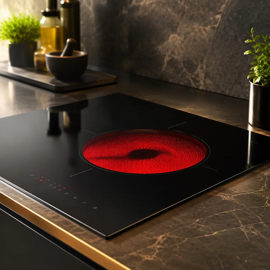
Induction cooking is now the default in premium kitchen ranges and standalone hobs, and appliance OEMs keep hitting the same set of board-level problems: EMC failures that appear only at the production line, IGBTs that die after a few months of thermal cycling, and touch controls that misfire near the high-current coil. The failures are almost never random. They trace back to layout decisions made before the board was ever routed.
At Huaxing PCBA we assemble high-power boards on 8 SMT lines and build from 2 to 32 layers, so we have deep experience with the mains-connected power stage and the isolation it demands.
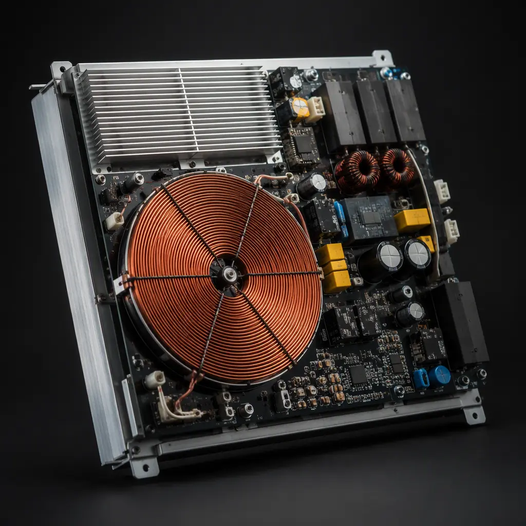
How Induction Heating Works at the Board Level
Induction cooktops drive a high-frequency current through a copper coil under the glass. The alternating magnetic field induces eddy currents in the ferromagnetic pan, which heat it directly. The board's job is to produce that high-frequency, high-current drive safely and efficiently. Three stages matter:
Mains Rectification and Filtering
AC mains is rectified to a high-voltage DC bus, typically around 310 V after a 230 V supply. A line filter (common-mode choke + X/Y capacitors) and a PFC stage are needed to meet conducted EMC limits. The layout of this stage is critical because it sits between the mains connector and the switching stage, keep the return loops tight and route the filter away from the switch node.
The Resonant Inverter
This is the heart of the induction cooktop. A resonant DC-AC converter (usually a half-bridge or full-bridge IGBT stage, or in single-burner designs a single-switch quasi-resonant topology) switches at 20-40 kHz. Because the coil works with the resonant capacitor, the switching is at a soft-switching point, which keeps losses low. The IGBTs and the resonant capacitor must be rated for the peak voltage and current, and the gate drive must be clean.
Control and User Interface
A microcontroller controls the power stage, reads the touch interface, and monitors temperature and pan detection. The control section is the low-side of the isolation barrier and must be kept away from the switch node's noise. See our EMI/EMC design guide for how to partition the high- and low-noise domains.
Choosing and Driving the IGBT
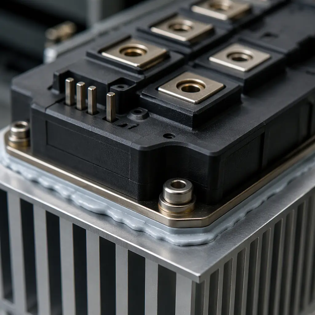
The power switch is the most-stressed component. Getting the IGBT right is a matter of matching its ratings to the real operating envelope, then driving it correctly.
Voltage and Current Ratings
For a 230 V mains, choose an IGBT with a collector-emitter voltage of at least 600 V . Never size it at the nominal bus voltage, because switching transients and resonance can push the bus well above the DC value. Consider the peak current that the coil drives under load, and allow margin for the resonant ring.
Gate Drive and Protection
The gate drive needs enough current to switch the IGBT quickly, and a careful gate resistor to control dv/dt. An anti-saturation / desaturation protection circuit protects against shoot-through. A gate-driver IC with the right isolation rating is mandatory if the gate is referenced to a floating node. See our power electronics PCB guide for the drive-stage rules.
Thermal Management of the Switches
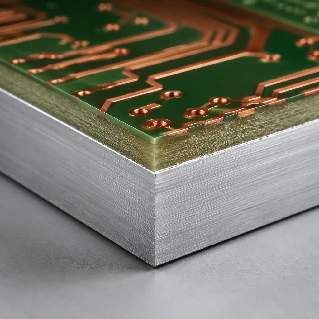
The IGBT dissipates significant heat, so it must be mounted to a heatsink through a good thermal interface. The PCB often uses an isolated metal substrate (IMS) or a dedicated heatsink area. For the highest-power burners, an IMS / metal-core PCB is used to conduct heat away efficiently. Plan the mounting and thermal path before routing the power section.
| Parameter | Typical Value | Design Note |
|---|---|---|
| Switching frequency | 20–40 kHz | Set by LC resonance; must stay in audible-safe band |
| IGBT voltage | 600–1200 V | Sized for transient, not just DC bus |
| DC bus (230V mains) | ~310 V | After rectification; margin for ripple |
| Input coil current | 15–25 A | Drives heavy copper/IMS choice |
| Mains creepage | ≥6 mm (primary-secondary) | IEC 60335-2-6 isolation requirement |
EMC and Mains Safety, IEC 60335-2-6
An induction cooktop is a mains-connected appliance, so it must comply with IEC 60335-2-6 (household electrical safety) and the relevant EMC standards. These are non-negotiable and drive as much of the design as the power stage itself.
Creepage and Clearance
Between the mains (primary) and the touch/control (secondary) side you need a creepage distance of at least 6 mm, often more for reinforced insulation. This is achieved by physical slotted barriers on the PCB and by keeping the control section fully separated from the power stage. See our certifications guide for how the isolation is documented.
EMC Filtering
The resonant inverter produces a lot of common-mode and differential-mode noise. A properly designed input filter (choke and capacitors) is essential to meet conducted emission limits. The filter must be placed before the rectifier, with the loop kept tight and routed away from the switch node. Our EMC compliance guide covers the filter topology and layout.
Thermal Protection and Derating
The appliance must be safe under fault conditions, which means robust temperature monitoring (NTC sensors) and firmware protection that shuts the inverter down if the IGBT or coil overheat. This is a requirement, not a nice-to-have. Our thermal management guide explains the sensing and derating approach.
Pan Detection and Sensing
Inductive sensing detects whether a suitable pan is present and sizes the power to the load. This requires a clean, low-noise return path for the sense signal, kept separate from the noise of the power loop. The coil is also used as a sensing element, so the detection circuitry must be well-isolated from the drive.
Assembly and Testing for a Mains Product
A mains-connected appliance PCB needs rigorous assembly and testing, not just a flying-probe check.
High-Voltage (Hipot) Testing
Every production board must pass a dielectric withstand test between the mains and the accessible parts. This catches assembly defects like solder bridges, flux residue, and incorrect insulation. See our testing methods guide for the full test list.
Functional and Burn-In Testing
Given the thermal stress, many OEMs run functional and burn-in testing. Our burn-in and ESS guide covers how to plan that. This is the difference between a board that ships and a board that ships with a known-good thermal profile.
Conformal Coating for Harsh Conditions
Kitchens are humid, greasy and hot. A conformal coating protects against moisture and contamination, but it must be applied so it doesn't bridge the mains creepage path. See our conformal coating guide for the correct specification.
Summary, Building a Reliable Induction Cooktop PCB
An induction cooktop is a synthesis of power electronics, isolation and EMC. Size the IGBT for the transient envelope, gate-drive it cleanly, keep the switch-node loop physically tight, put a real line filter in front of the rectifier, and isolate the control and sense domains from the power loop. Then test the finished assembly with hipot, functional and thermal checks. Do that, and the hot plate of your cooktop stays on the glass, not on the board.
At Huaxing PCBA we assemble mains-connected power boards on 8 SMT lines with IATF 16949 and ISO 9001 certified quality systems, supporting IMS/metal-core construction and IPC Class 2/3 acceptance. We offer a free DFM review on the isolation, EMC and thermal design of your appliance board, so it passes certification cleanly. Send your files for a quote or talk to an engineer about your cooktop and appliance PCB.
