

An indoor air quality monitor measures carbon dioxide, particulate matter and volatile organic compounds so a building can adjust its ventilation, a facility can prove its environment, and an occupant can trust the air. Because those numbers feed real decisions, and in some markets compliance reporting, the board behind the sensors has to return measurements that are accurate today and still accurate six months from now. That is a harder problem than it looks.
The challenge is that each IAQ sensor type has a different physics and a different electronics. An NDIR carbon dioxide sensor is an optical device with a pulsed IR source. A PM2.5 sensor is a laser scattering instrument. A VOC sensor is a heated metal-oxide resistor. Putting all three on one board is a mixed-signal, thermally-managed, optically-careful engineering problem, exactly the kind we build at Huaxing PCBA, where our 8 SMT lines run a 98.7% first-pass yield across 150+ active customers and our 3/3 mil trace control supports dense analogue front-ends.
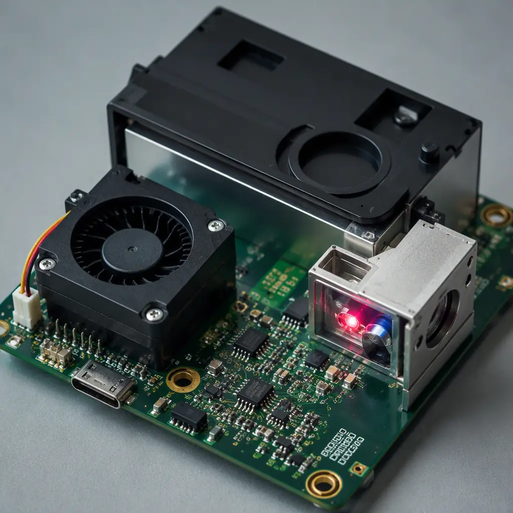
The Three Sensing Technologies and Their Different Electrical Needs
The sensor choice drives the whole board. Each technology imposes a different supply, routing and layout constraint, and the constraints can conflict. Understanding what each one needs is the first step to a design that does not fight itself.
| Pollutant | Typical sensor | Measured range | Key electrical need |
|---|---|---|---|
| CO2 | NDIR (non-dispersive infrared) | 400–5000 ppm | Stable pulsed IR drive, precise ADC, clean supply |
| PM2.5 | Laser scattering | 0–1000 µg/m³ | Fan control, photodiode readout, low optical noise |
| VOC | MOX (metal-oxide) | 0.3–100 ppb eq. | Heated element, baseline drift handling, gas isolation |
| Temp / RH | MEMS / capacitive | Fully ranging | Calibration reference, I2C, low-power |
NDIR CO2: Optical and Analogue Discipline
A non-dispersive infrared carbon dioxide sensor works by shining a broadband IR source through a sample and measuring how much light a specific wavelength band absorbs. The narrowband detection makes CO2 stand out from other gases. But the measurement is tiny, so the board has to be quiet and the optical path has to be sealed.
Pulsed source drive and temperature
The IR lamp is pulsed to save power and to reject ambient drift. The pulse timing must be deterministic and the lamp voltage stable, because the source intensity sets the reference. The sensor is also temperature-sensitive, so a temperature reading at the sensor is needed to correct the absorption curve.
Precise ADC and a quiet analogue path
CO2 concentration is derived from a small difference in a small photodiode signal. That demands a low-noise amplifier and a precise ADC, with the analogue area isolated from the switching noise of the lamp drive and from any digital activity. This is textbook mixed-signal layout, see our mixed-signal PCB design guide for the partitioning and grounding rules.
Sealing the optical path
The sample chamber has to be sealed to prevent light leakage from outside, and it usually needs a dust filter so particles do not settle on the optics. This is a mechanical requirement that the board layout has to accommodate. The enclosure, the filter and the sensor mount are all part of the measurement.
Key Takeaway: The CO2 channel is the most demanding. It is a precision optical measurement with a microvolt-scale signal, so the layout must isolate the analogue detection path from the lamp drive and from digital switching, and the design must seal the optical chamber.
PM2.5: Laser Scattering, Fan Control and Clean Sampling
A PM2.5 sensor draws air through a small chamber, passes it through a laser, and counts and sizes particles by the light they scatter onto a detector. The laser and detector have to stay optically aligned, and the airflow has to be repeatable and clean.
Airflow and the fan
The measurement depends on a known volume of air passing through the chamber at a known rate, so the fan drive and its speed control matter. A fan that changes speed, or that is too noisy, corrupts the count. Fan control is a small motor-drive task, and our BLDC motor controller design guide covers the drive side.
Detector readout and photodiode noise
The scattered light is detected by a photodiode whose current is tiny. The readout has to be stable and well-shielded from the laser drive and from the fan's switching noise. Keeping the detector readout away from sources of electrical noise is essential to a clean particle-size histogram.
Optical cleanliness over time
Dust accumulates on the optics and on the detector, which makes the reading drift downward over a long service life. The design has to allow for cleaning or self-calibration, and the sampling path should be protected from gross contamination.
VOC: Metal-Oxide Baseline Drift and Gas Isolation
A metal-oxide VOC sensor is a heater plus a sensitive film. The film changes resistance when it adsorbs certain molecules, and that resistance is the measurement. The sensor runs hot, which means the board must keep the heat away from the CO2 and temperature sensor, and the reading drifts with the baseline, so the design needs a way to manage that.
Thermal separation
The MOX heating element can reach 300–350°C internally to drive the sensing reaction. That heat must not skew the temperature and humidity sensor or the CO2 measurement. In practice this means careful placement and, where necessary, an insulating barrier or a thermal budget that keeps the two apart.
Baseline handling
MOX readings drift as the sensor ages and as environmental conditions change. Robust designs apply a periodic baseline correction, often using a known-clean-air reference. Firmware and hardware work together here. The board has to expose the sensor to a reference periodically, and the layout should make that possible.
Supply regulation
The heater and the sensing film are both sensitive to supply fluctuations. A noisy or drooping supply corrupts the resistance reading, so the sensor supply needs clean regulation. Our power integrity and PDN design guide covers the decoupling and regulation discipline this needs.
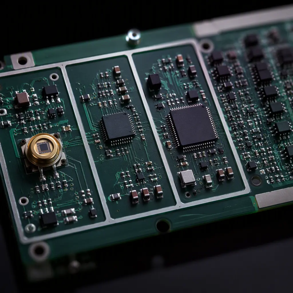
The common thread across all three channels is supply hygiene and analogue isolation. The reading quality of an IAQ board is set by how well the analogue front-ends are separated from the digital, the switching and the thermal sources on the same board. The EMI/EMC design guide and the mixed-signal design article together cover the discipline that makes this work.
Calibration, Accuracy and Long-Term Stability
Every sensing element drifts and every sensor has a factory tolerance. For an instrument that reports to a user or a compliance system, the board has to support a way to zero it, and the measurement chain has to be designed so the reported number means something.
| Sensor | Typical accuracy | Drift concern | Board-level mitigation |
|---|---|---|---|
| CO2 (NDIR) | ±40–50 ppm | Lamp aging, temperature | Temperature correction, periodic auto-calibration to fresh air (~400 ppm) |
| PM2.5 (laser) | ±10 µg/m³ | Optics fouling | Cleanable path, allowance for cleaning |
| VOC (MOX) | Relative ppb scale | Baseline and aging | Periodic baseline correction, reference exposure |
| Temp / RH | ±0.3°C, ±2%RH | Low | Calibration value stored at factory |
For a board that is used in a product, the practical question is whether the layout gives the firmware room to calibrate and whether the sensor interfaces are accessible and stable. A board that cannot be zeroed, or whose readings wobble with a change in fan speed, will never be trusted no matter how precise the sensor datasheet is.
Design-for-Manufacture on a Dense Sensor Board
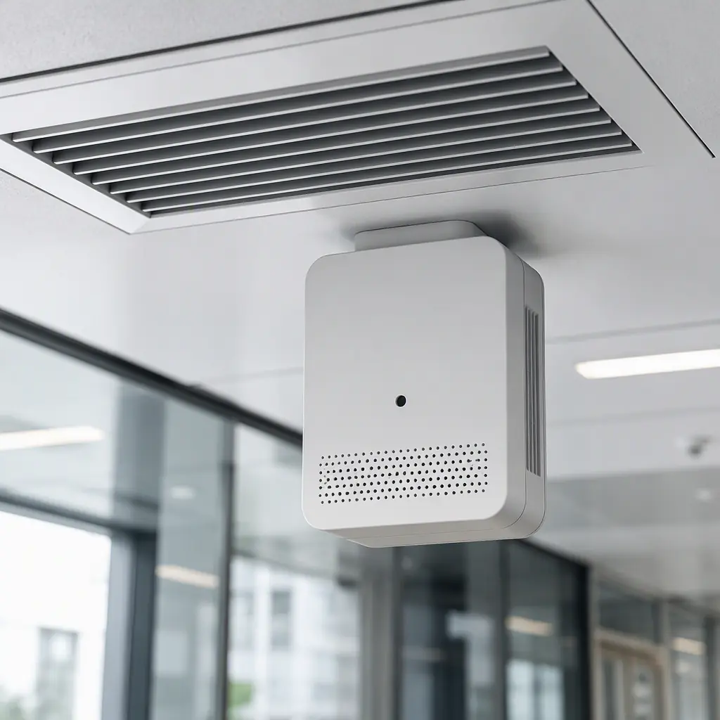
An IAQ monitor is a small, dense, mixed-signal board with an optical sub-assembly and a mechanical airflow path. It is exactly the kind of design where manufacturability interacts with performance: an aperture that is too tight, a component that blocks the airflow, or an optical part that cannot be aligned in production all hurt the final product. Running the DFM tips and a structured assembly process review before the first run catches these issues.
Procurement Tip: When you source an IAQ board, ask the supplier how they handle the CO2 optical alignment and the VOC thermal separation in production. These are the two areas where a cheap board announces itself with unstable readings, and they are findable with a proper DFM review before the first run.
At Huaxing PCBA we build precision sensor and environmental-monitoring boards with 8 SMT lines, 4 DIP lines, 32-layer fabrication and 3/3 mil trace control, in a 15,000 m² facility with 500+ staff serving 30+ countries. We are ISO 9001, IATF 16949 and UL (E354321) certified, with 99.2% on-time delivery and 98.7% first-pass yield. Upload your design for a quote or talk to our engineering team about your sensor board. For the wider context, see our IoT PCB and IIoT gateway guides.
