
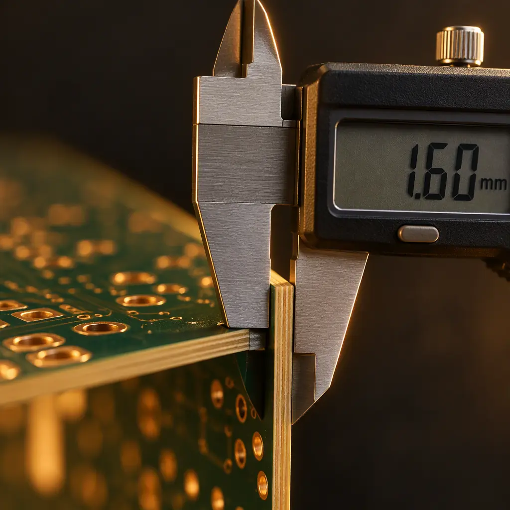
A supplier sends you a first-article inspection report. Every dimension is inside tolerance, the report is signed and dated, and the lot ships. Six weeks later your own incoming inspection finds hole diameters drifting out of specification. Nothing was falsified and nobody lied — and yet the two organisations measured the same parts and reached different conclusions. The reason is almost always the measurement system, not the parts.
This is the gap that Gauge R&R and Measurement System Analysis exist to close, and it is the single most under-specified requirement in B2B electronics procurement. Buyers routinely demand tolerance compliance from suppliers without ever asking whether the instrument used to demonstrate that compliance is capable of resolving the tolerance in the first place. At Huaxing PCBA we qualify the measurement systems on our CMM, optical comparators and AOI stations before we quote against customer tolerances, because a measurement we cannot defend is worse than no measurement at all.
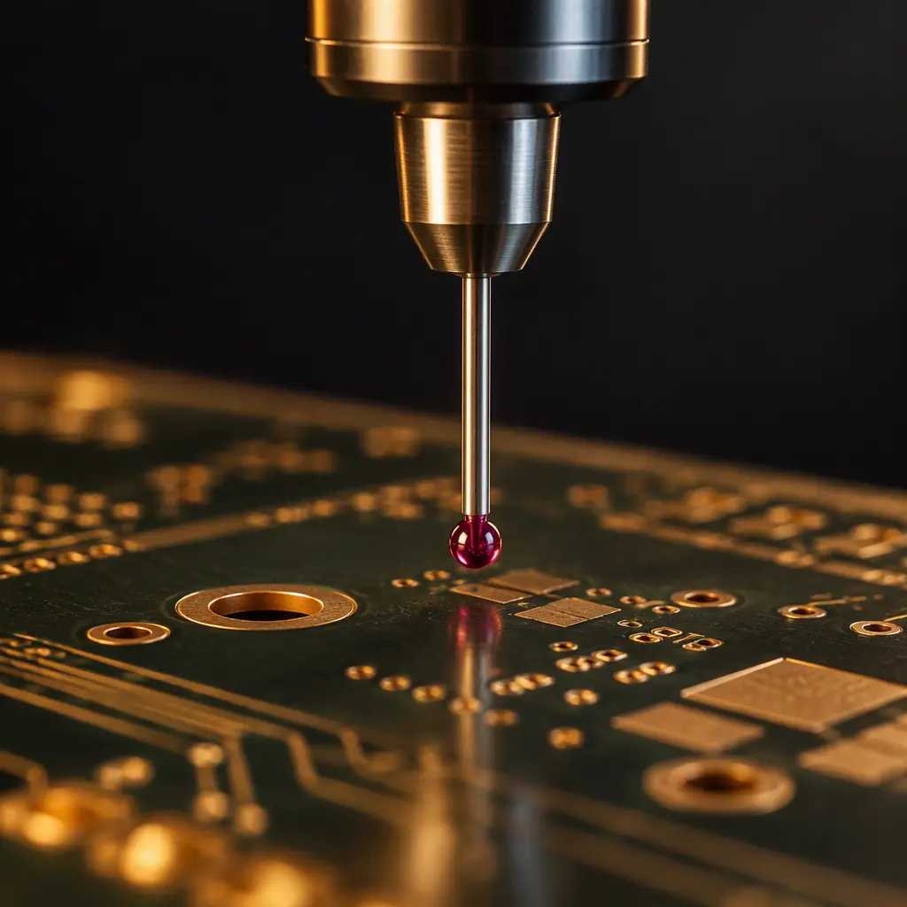
The Core Problem: Measurement Error Consumes Tolerance
A drawing tolerance is a promise about the part. A measurement system is how you verify that promise — but the measurement system has its own error, and that error is spent out of the same tolerance budget. If your drawing allows a hole diameter of 1.00 ± 0.05 mm, you have 0.10 mm of allowance to spend. Every micron of measurement variation eats into it.
The industry convention, formalised in the AIAG measurement systems reference manual and widely applied to electronics manufacturing, expresses measurement error as a percentage of the tolerance band. That single number, %GRR, is the whole conversation.
| %GRR of tolerance | Verdict | What it means commercially |
|---|---|---|
| Under 10% | Acceptable | The system resolves your tolerance comfortably. Accept inspection data at face value. |
| 10 to 20% | Conditionally acceptable | Workable, but depends on the criticality of the characteristic. Request justification for margin-critical dimensions. |
| 20 to 30% | Not acceptable | Data cannot support tolerance decisions. Demand instrument, method or tolerance change. |
| Over 30% | Reject the measurement system | Inspection is effectively a coin toss. Re-measure with a qualified system before accepting parts. |
Key Takeaway: %GRR is a ratio, not an absolute. It depends on the tolerance you specified. Tighten a tolerance by half and you can double %GRR without changing the instrument a single micron — which means the same caliper that was acceptable on your last program may be unfit on this one. Always specify %GRR limits relative to the drawing tolerance, never as an abstract requirement in a quality clause.
What Gauge R&R Actually Measures
The "R&R" stands for repeatability and reproducibility, and the distinction between them is where most quality arguments go wrong. A Gauge R&R study separates these two components, plus the part-to-part variation that should dominate if your process is behaving.
Repeatability — same operator, same instrument, same part
Also called equipment variation. One inspector measures the same feature repeatedly with the same instrument and the readings scatter. That scatter is inherent to the gauge, the fixturing and the measurement method. A common cause in PCB metrology is inadequate support of the board: a thin panel measured on a CMM without proper fixturing flexes under the probe, and the apparent repeatability problem is really a clamping problem. Our guide to PCB manufacturing tolerances covers which dimensions are realistically measurable at each tolerance band.
Reproducibility — different operators, same instrument and part
Also called appraiser variation. Two inspectors measure the same ten boards and one consistently reads 0.02 mm higher than the other. This is a training, technique or interpretation problem — for example, whether a hole diameter is measured at the barrel or at the surface, or whether solder mask encroachment is included in a pad measurement. It is by far the more common failure mode in electronics, because a PCB has many features whose measurement datum is a judgement call rather than a physical edge.
Part variation — the signal you are trying to detect
If the parts you selected for the study are all essentially identical, the study cannot separate measurement noise from real variation and the result is meaningless. Good practice is to select samples spanning the full expected process range, not ten units from the middle of a stable lot. We deliberately include known out-of-tolerance samples in MSA studies so the system has a real signal to resolve.
Bias and linearity — the error that never averages out
Bias is a consistent offset from the true value, verified against a traceable reference. Linearity describes whether that bias changes across the measuring range. A gauge can be repeatable to a micron and still be biased by 0.03 mm if it was never calibrated against a traceable standard. Repeatability alone is not accuracy — a stopped clock is perfectly repeatable.
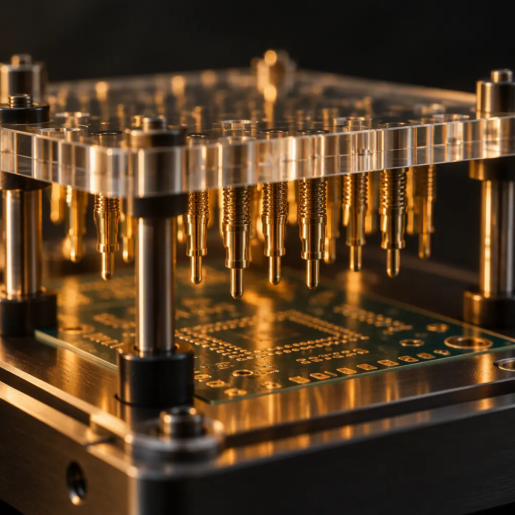
Which Measurements on a PCB Programme Need MSA
Not every characteristic justifies a full study. MSA effort should be allocated in proportion to how much a wrong decision costs, and in a PCB programme the candidates cluster into a few groups.
| Characteristic | Typical tolerance | Why MSA matters |
|---|---|---|
| Finished hole diameter (PTH) | ±0.075 mm | Drives component fit and press-fit pin retention; CMM or pin gauge must resolve well under the band |
| Impedance (controlled impedance traces) | ±10% of target | TDR measurement setup, probe calibration and coupon design dominate the reading |
| Copper trace width | ±20% (IPC Class 2) | Optical measurement is affected by edge roughness and etch factor; operator technique varies widely |
| Solder joint fillet / void percentage | Per IPC-A-610 class | X-ray void measurement depends heavily on threshold settings and operator judgement |
| Board thickness and warpage | ±10% / 0.75% max | Temperature and support conditions change the reading materially |
| Gold finger / edge plating thickness | Per finish spec | XRF spot placement on small features introduces large reproducibility error |
Void percentage in solder joints deserves a specific caution. It is one of the most argued-about numbers in PCBA because it is genuinely difficult to measure reproducibly. Different X-ray systems with different grey-level thresholds applied to the same joint can report void fractions that differ by a factor of two. When you see a void specification in an acceptance document, the right follow-up question is not "what is the limit" but "what is your %GRR on that measurement". Our guide to AOI, X-ray and SPI inspection covers how these systems are used in practice.

How to Ask for an MSA Study Without Being Ignored
Requesting "an MSA" as a bare quality clause usually produces either silence or a generic calibration certificate, because calibration and MSA are different things and many suppliers conflate them. A calibration certificate proves the instrument matched a reference on the day it was calibrated. It says nothing about whether two operators interpret a feature the same way. Write the requirement concretely instead.
Name the characteristic and the drawing tolerance
Ask for a %GRR figure on a specific dimension with its tolerance band quoted, for example finished hole diameter to ±0.075 mm. This forces a meaningful denominator and makes the answer comparable across suppliers. Vague requests attract vague responses.
Specify the study design
The standard crossed design is 10 parts, 3 operators, 3 trials. State it, and state that samples should span the process range. If you leave the design open, expect a 3-part study that proves nothing. Our AQL sampling guide covers the parallel question of how many units to inspect for lot acceptance, which is a separate decision from how many to study for measurement capability.
Ask for the ANOVA output, not just the headline number
A single %GRR number hides which component failed. If %GRR is 24 per cent because repeatability is poor, the fix is fixturing or the instrument. If it is 24 per cent because reproducibility is poor, the fix is training or a written measurement procedure. Requesting the repeatability and reproducibility split tells you which conversation to have. Ask whether the study was analysed by average-and-range or ANOVA — ANOVA handles interaction between operator and part, which the simpler method ignores.
Tie it to the PPAP or qualification submission
MSA belongs inside the qualification package, alongside capability studies and the control plan, not as an afterthought. If your supplier runs a PPAP-style submission, the MSA is one of its required elements — our PPAP guide for PCB suppliers lists what the full package contains, and the supplier audit guide shows how to verify the capability claims during a site visit.
Set a consequence for the answer
Decide in advance what you will do if %GRR comes back above 30 per cent. The options are to widen the tolerance if the drawing allows it, fund a better measurement method, or agree on an alternative acceptance approach such as functional test. Without a pre-agreed consequence the study becomes paperwork. Our quality dispute resolution guide covers how measurement disagreement clauses are normally worded.
What a Failing MSA Means for a Lot Already in Transit
A failed MSA does not automatically mean the parts are bad — it means you cannot currently prove they are good. Those are different problems with different responses, and conflating them causes either over-reaction or dangerous complacency.
The practical sequence is to re-measure a sample using an independent, qualified system. If the parts pass on the better system, the lot is likely conforming and the issue is documentation and future method. If they fail on the better system, you have a genuine quality escape. Either way, the corrective action is on the measurement method, and the lot disposition decision should be made on the qualified data — not on the original report. Our failure analysis guide and incoming quality inspection guide cover the disposition workflow from there.
Factory reality check: On impedance-controlled boards we will not quote a ±8 per cent impedance tolerance unless the customer accepts a defined test coupon and a specified TDR setup, because the measurement method contributes a material fraction of that band. Loosening to ±10 per cent with an agreed coupon is usually the right commercial outcome — the electrical performance is unaffected in most digital designs, and both parties can defend the number. A specification nobody can measure reliably is not a tighter specification; it is an invitation to argue.
Summary and Next Steps
Gauge R&R answers a question that tolerance compliance cannot: whether the measurement system used to prove compliance is capable of resolving the tolerance at all. Specify %GRR against your actual drawing tolerance, require a standard 10-part three-operator study with the repeatability and reproducibility split reported, and place it inside the qualification package where it belongs. A 30 per cent %GRR on a critical dimension is not a paperwork problem — it is a signal that the acceptance decision on that feature is currently unsupported.
At Huaxing PCBA our CMM, optical comparator and XRF systems are qualified by MSA before they are used to accept customer tolerances, and we will share the study output on request with any quotation. Our facilities hold IATF 16949 and ISO 9001 certification across 8 SMT lines and 32-layer fabrication. Read our PPAP guide for PCB suppliers or send your drawing and ask for the MSA data — we will return the study alongside your quote within 24 hours.
