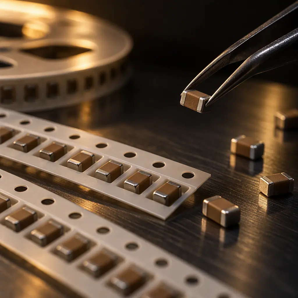
A 100 nF X7R capacitor bought as 100 nF is rarely 100 nF on the board. At its rated 16 V it may be holding 40 nF, it has lost a few percent since the reel was sealed, and it will lose a few more before the product finishes its qualification run. None of those three losses appear on a bill of materials, and all three are the supplier's problem only if the purchase order says so.
This is the selection problem that separates a design that passes at bench voltage from one that passes in the field. It is also the area where buyers most often discover, at incoming inspection, that they have no agreed way to decide whether a reel is acceptable.
What Dielectric Class Actually Commits You To
Ceramic capacitors divide into two families, and the difference is not quality but contract. Class I dielectrics such as C0G and NP0 hold their capacitance with almost no drift, and their temperature coefficient is specified in parts per million per degree Celsius. Class II dielectrics, which is everything sold as X7R, X5R, Y5V or Z5U, offer ten to a hundred times the capacitance per volume and pay for it with three behaviours that must be engineered around: temperature drift, DC bias loss and ageing.
| Class | Typical range | Temperature drift | DC bias loss | Use it for |
|---|---|---|---|---|
| C0G / NP0 | 1 pF - 100 nF | ±30 ppm/°C | negligible | Filters, oscillators, timing, RF matching |
| X7R | 100 pF - 22 uF | ±15% over -55 to +125 °C | 20-70% | General decoupling, industrial and automotive |
| X5R | 100 pF - 100 uF | ±15% over -55 to +85 °C | 40-80% | Bulk on space-constrained boards, consumer |
| Y5V | 10 nF - 10 uF | +22% / -82% | up to 90% | Cost-only positions, non-critical filtering |
The letter code is a promise about a range, not about a value. X7R means the part stays within plus or minus 15 percent of its nominal capacitance between minus 55 and plus 125 degrees Celsius, measured at zero bias and at low measurement voltage. It says nothing about what the part does at 12 volts. That is a separate curve, published per case size and per voltage rating, and it is the curve buyers almost never ask for.
DC-Bias: The Loss Nobody Puts in the BOM
Class II ceramics are made from barium titanate, whose dielectric constant falls as the electric field across it rises. In a small package with thin dielectric, the field at rated voltage is high, so the loss is large. A 0603 X5R rated at 6.3 V can retain less than a third of its nominal capacitance at 5 V. The same value in a larger case with a higher voltage rating may retain eighty percent or more.
| Measured case (our bench, 25 °C, 1 kHz, 1 V rms stimulus) | Nominal | At 25% rated V | At 50% rated V | At rated V |
|---|---|---|---|---|
| 0402 X5R 6.3 V, 100 nF | 100 nF | 78 nF | 55 nF | 31 nF |
| 0402 X7R 16 V, 100 nF | 100 nF | 92 nF | 76 nF | 54 nF |
| 0603 X7R 25 V, 100 nF | 100 nF | 96 nF | 86 nF | 71 nF |
| 0603 X5R 6.3 V, 10 uF | 9.8 uF | 6.1 uF | 3.4 uF | 1.6 uF |
| 0805 X7R 50 V, 1 uF | 980 nF | 950 nF | 900 nF | 810 nF |
Rule of thumb: for a Class II part used above half its rated voltage, assume you have 60 percent of the nameplate value and size the position accordingly. If the design cannot tolerate that assumption, the part should be C0G, a larger case, or a higher voltage rating — in that order of cost.
There is a second-order effect that catches designers on high-current rails. The bias loss depends on the instantaneous voltage across the part, so on a rail with significant ripple the capacitance is modulating with the load. On a 12 V rail with 1 V of ripple, a capacitor sitting at 11.5 V behaves differently from the same part at 12.5 V. On bulk positions this can turn a comfortable stability margin into a marginal one, which is why regulator loop compensation is specified against the effective capacitance and not the BOM value.
Voltage Derating by Application
Derating is the practice of running a capacitor well below its rated voltage so that bias loss, breakdown margin and long-term wear all stay inside budget. There is no universal number, because the acceptable margin depends on what happens when the part fails and how the product is used.
| Application | Recommended max working voltage vs rating | Driver |
|---|---|---|
| Consumer, benign indoor | 80% | Cost driven, low field stress |
| Industrial control, 24 V plant | 70% | Continuous duty, wide ambient |
| Automotive under-hood | 50% | AEC-Q200 grades, thermal cycling, vibration |
| Medical, mains-adjacent | 50% | Failure mode must be benign |
| Aerospace, defence | 50% | Derating standards, single-fault tolerance |
| Telecom and datacom line cards | 60% | Continuous duty, high ambient in cabinets |
| Energy storage and inverter DC link | 50-60% | Ripple current heating, long service life |
These are working figures, not a substitute for the customer's own derating standard. Where a customer has one — a defence programme, an automotive tier-one specification, an aerospace DO-254 derived requirement — that standard governs and the supplier's job is to demonstrate compliance rather than to argue about it. What the supplier should never do is quietly substitute a 16 V part for a 25 V part because the 16 V was in stock. That substitution is electrically invisible on a bench test and is one of the commonest causes of a field return that cannot be reproduced.
Ageing, Solder Shift and Shelf Life
Class II ceramics lose capacitance logarithmically with time at a predictable rate, typically one to three percent per decade hour at room temperature, and faster at elevated temperature. A part that measured 100 nF at the factory may be 96 nF after a year on the shelf. The mechanism is not damage; it is the gradual reordering of the crystal structure, and it resets when the part is heated above its Curie temperature.
That reset is why the reflow profile matters to a capacitor buyer. Every part that goes through reflow comes out of the oven with its capacitance restored to nearly nominal, then begins ageing again from that moment. Two consequences follow. First, measuring capacitance at incoming inspection on a reel tells you about the part as shipped, not as it will behave two years later. Second, a board measured immediately after assembly will read slightly high against the same board measured after a year in a warehouse.
For a two-year build programme this is a real planning input. If a design relies on 95 percent of the nominal value, it will not hold that margin for the life of the programme. Either the margin is designed in as an allowance for ageing, or the part specification is written against the minimum value the design needs rather than the nominal.
Incoming Verification: What a CM Should Measure on Every Reel
A capacitor that is not what the label says is a failure mode that neither the designer nor the fabricator will catch by looking at the board. Verification at receipt is therefore the only point where the reel itself can be checked, and it should be written into the purchase order rather than assumed.
- Marking and packaging: part number, date code, lot, quantity, reel orientation, moisture barrier condition, and a humidity indicator card that is still in the dry state
- Dimensional check per AQL sample: case size, thickness and terminal band width against the drawing, measured on a sample drawn across the reel rather than from the first cut
- Capacitance and dissipation factor on the AQL sample at 1 kHz or 1 MHz as the series specifies, recorded against the nominal and the tolerance band
- Insulation resistance or leakage current at rated voltage, which catches the parts that pass a capacitance test but have a damaged dielectric
- Solderability per J-STD-002 on a sample from every lot, because a reel that has absorbed moisture or oxidised will fail at reflow rather than at inspection
- Traceability link from the reel label to the lot certificate, which is what makes the rest of the evidence usable in a failure investigation
The AQL level and sample size should be agreed in advance. A common and defensible arrangement for passive components is general inspection level II with an AQL of 0.65 for major defects and 1.5 for minor, sampled per lot rather than per shipment. What matters is not the exact number but that the buyer and the supplier are using the same number, because a dispute about a reel is otherwise settled by whoever has more patience.
Counterfeit and Re-Marked Parts
Passive components are counterfeited less often than active devices, but re-marking and re-reeling of salvaged or out-of-specification parts is common enough that the verification above is worth doing. The strongest single check on a suspicious lot is X-ray fluorescence on the terminal finish, which identifies the plating composition and will show a part that claims a nickel barrier but has none. Date-code logic is the second: a date code that is older than the programme, or that does not match the packaging style of that era, is a reason to hold the lot rather than to accept it.
A certificate of conformance is worth exactly what the issuer's reputation is worth. It proves that someone signed a document; it does not prove that the parts in the box are the parts on the certificate. Buyers who treat a certificate as the verification step are the ones who discover the problem at functional test. The verification procedure above, applied to a sample per lot, is a materially stronger position for the same effort.
The Five-Line Capacitor Spec for Your BOM
A capacitor specification that can actually be enforced in production fits in five lines: dielectric class and tolerance, voltage rating plus the maximum working voltage allowed by the application derating rule, case size with a note that substitution to a smaller case requires approval, the minimum effective capacitance at operating voltage rather than the nominal value, and the verification requirement at receipt including AQL and the tests to be run. That last line is the one that turns a specification into a control.
If those five lines are agreed before the first purchase order, most capacitor-related arguments never happen. If they are agreed after a field return, they cost considerably more.
What to Ask Your Assembly Supplier
Ask for the derating rule the supplier applies when it substitutes a part, and get it in writing. Ask whether incoming inspection includes electrical measurement or only a visual and quantity check. Ask for the AQL and the sample plan. Ask how a reel is quarantined when it fails, and who is notified. A supplier that can answer those four questions has a process; one that answers with a certificate and a reassurance does not.
Our own position is that substitution without written approval is a defect regardless of whether the substitute works, because the approval record is what makes the next build repeatable. Buyers who want the wider cost picture should read our guide to BOM cost reduction strategies, which treats alternates as a controlled process rather than a sourcing shortcut. Where counterfeit risk is the specific concern, the counterfeit verification guide covers the inspection methods in more depth, and the IPC-1782 traceability guide explains how reel-level records connect to the finished assembly.
Get Your BOM Checked Before You Release It
Send us the BOM with the capacitor lines and the operating conditions for each rail. We will flag positions where the derating is marginal, where the effective capacitance at operating voltage is below what the circuit needs, and where a substitution would change the electrical behaviour. That review happens before tooling is released, which is the only point at which it is free.