

Conductive anodic filament, or CAF, is one of the least photographed and most expensive failure modes in electronics. It does not fail during burn-in, it does not show on a flying-probe or ICT fixture, and it does not complain during incoming inspection. It grows slowly, over months, and when it finally makes contact it looks like an intermittent low resistance that is almost impossible to reproduce on a bench.
For a product deployed in high humidity, telecom, automotive or power-electronics environments, CAF is a genuine reliability gate. Huaxing PCBA builds boards on 8 SMT lines with 32-layer capability and IPC-A-610 Class 3 and IATF 16949 quality systems, and we run CAF characterisation on high-risk laminates before we commit a design to volume. This guide explains the mechanism, the test, and the design and material decisions that stop it.
What Is CAF And Why Does It Matter?
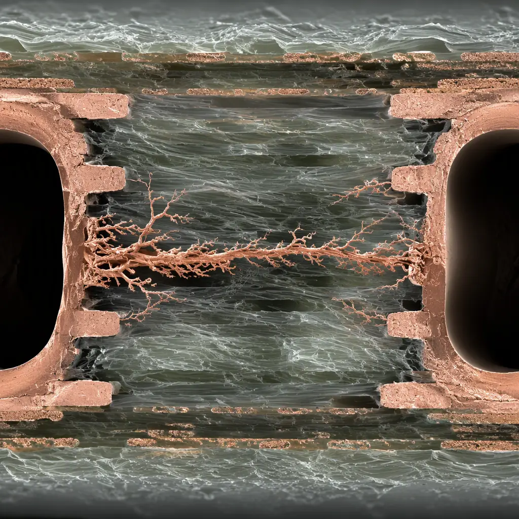
CAF is a copper-based filament that precipitates out of solution and grows along the glass fibres inside a laminate. Under a bias voltage and with moisture present, copper ions leave the anode, migrate through or along the fibre-glass weave, and form a conductive bridge to a lower-potential conductor. The result is a leakage path that can end as a hard short.
Because the growth is ionic and driven by both voltage and humidity, CAF is a field failure. A board that passed a 100 MΩ insulation check in a clean factory can read a few hundred ohms after a humid summer. The catastrophic version, a through-hole to through-hole or inner-layer to inner-layer short, takes the whole product down with no warning.
It Is A Migration, Not A Manufacturing Defect
CAF is not caused by a broken drill or a solder splash. It is an electro-chemical migration process that depends on laminate quality, spacing, humidity and bias voltage. That is why it can happen on a board that is otherwise perfect. And why the mitigation is in the design and material choice, not the soldering.
The Three Conditions That Create It
CAF needs all three at once: (1) a condensed moisture path, typically inside the laminate or along a drilled hole wall, (2) a potential difference between two conductors, and (3) a route along the glass fibre that lets copper migrate. Remove any one and the process stops.
Where CAF Actually Grows
CAF does not grow uniformly. It needs adjacent conductors with a voltage between them and a physical path for the ions. Knowing where it concentrates tells you where to spend your design margin.
Through-Hole To Through-Hole
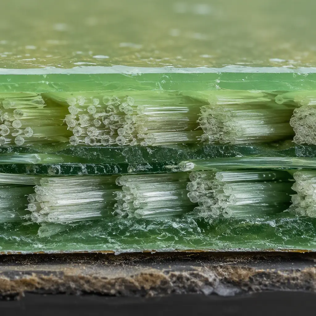
The classic case. Two vias or two plated holes that sit too close together, with the glass fibre of the laminate between them acting as the migration highway. This is why minimum hole-to-hole spacing is a CAF-relevant DFM rule, not just a drill-tolerance rule. See our drilling tolerance guide.
Inner Layer To Inner Layer
On multilayer boards, opposite nets on adjacent layers are separated by a thin dielectric. When that dielectric gets wet and stressed, a filament can cross the resin between the copper planes. Microvia and HDI boards with ultra-thin dielectrics need explicit CAF review, see our microvia reliability guide.
Along A Single Trace Or Hole Wall
CAF also follows the grain of the glass bundle running parallel to a slot, or tracks along the wall of an insufficiently-de-smeared hole. A rough, resin-starved hole wall is a preferred nucleation site, which is why hole quality and cleanliness feed directly into CAF resistance.
How CAF Is Tested, IPC-TM-650 Method 2.6.25
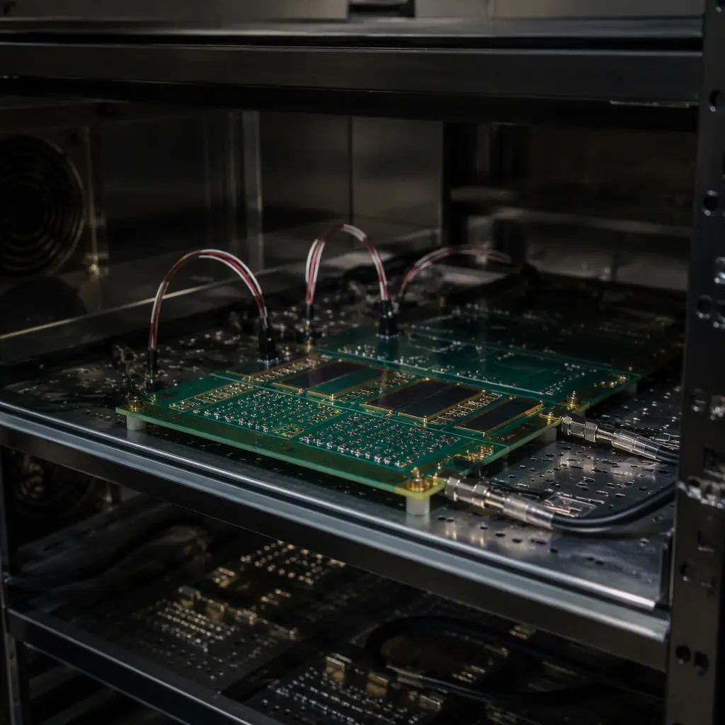
CAF resistance is not something you can measure with a multimeter. It is a lifetime property, so it is assessed with an accelerated stress test. The industry standard is IPC-TM-650 Method 2.6.25, which evaluates the susceptibility of a laminate to conductive anodic filament growth.
The test applies a DC bias between conductors while the coupon is exposed to temperature and humidity, then monitors the insulation resistance over time. A resistance collapse below a threshold indicates CAF growth. The pass/fail line and the test bias are set by the material supplier or by your own specification.
| Parameter | Typical CAF Test Setting | Why It Is Set This Way |
|---|---|---|
| Bias voltage | 100 V to 500 V DC | Field bias drives ionic migration |
| Temperature | 60–85 °C | Accelerates reaction kinetics |
| Relative humidity | 85–90% RH | Moisture is the transport medium |
| Criteria | Insulation resistance above ~10 MΩ | Large drop = CAF bridge forming |
In practice, the coupon is a test piece with a specific conductor pattern, and the test runs for hundreds of hours. The real question you want answered is not "does it pass today". It is "what is the margin between the design's field condition and the onset of growth". That margin is where you buy reliability.
Design And Material Rules That Prevent CAF
You cannot beat CAF after the fact, you engineer against it at the design table and at laminate selection. These are the levers that actually move the failure threshold.
Enough Spacing Between Opposing Nets
The single most effective control. Increase hole-to-hole spacing and inner-layer clearance so that the anodic-to-cathodic distance exceeds what the field can bridge. As a rule of thumb, keep high-bias nets on the same layer and avoid nested opposing voltages in a tight dense area.
Choose A CAF-Resistant Laminate
Not all FR-4 is equal. A high-Tg laminate with a higher resin content and a tighter glass weave is far more CAF-resistant than a general-purpose low-cost laminate. The resin fills the glass fibre paths that a filament would like to follow, and a lower moisture absorption rating slows the transport mechanism. See our laminate selection guide and materials guide.
Control Humidity At The Product Level
CAF needs moisture at the point of migration. Conformal coating, an effective enclosure seal and proper edge sealing all reduce the water that ever reaches the laminate. On a high-moisture design, coat the board and do not rely on the housing alone. See our conformal coating guide.
Name The Net Voltages That Matter
High-voltage nets, AC mains and switching nodes are the drivers. Identify the nets with the largest DC bias between closely-spaced conductors and give them a dedicated clearance budget. Tables like our creepage and clearance guide give the working distances for the voltage you are dealing with.
Watch The Dense Inner Layers
HDI and microvia boards use very thin dielectric between layers, which shortens the migration path and raises CAF risk. On these designs, pair a CAF-tested laminate with an adequate layer-to-layer separation and a qualified via process. Our microvia reliability guide and HDI technology guide cover the limits.
What To Verify In A Supplier
CAF is the kind of reliability factor you cannot verify with a bench test, so procurement has to probe the supplier's material and process discipline. These questions separate a supplier that has thought about CAF from one that has not.
| Question | What A Good Answer Sounds Like |
|---|---|
| Which laminate, and is it CAF-tested? | A named high-Tg FR-4 with an IPC-TM-650 2.6.25 datasheet value |
| What is your minimum hole-to-hole spacing? | A stated DFM limit that varies with layer-count and working voltage |
| Do you run accelerated CAF testing? | Yes, on the laminate class you are committing to, with a documented result |
| How is inner-layer registration and dielectric thickness controlled? | A registered process with an in-process dielectric measurement and a standard tolerance |
If the supplier only lists "FR-4" without a CAF specification, and treats spacing as a single catch-all rule, push for the numbers, especially for a design with high voltages or a long service life in a damp location. The difference between a generic board and a CAF-hardened one is often invisible on the quote.
Summary, Buy The Margin, Not The Part
CAF does not announce itself, but it is entirely avoidable. Keep opposing high-bias nets apart, choose a CAF-resistant high-resin laminate, control humidity at the enclosure and coating level, and give the dense inner layers a real clearance budget. Then hold your supplier to a named laminate with a tested CAF value rather than a hand-wave about quality.
At Huaxing PCBA we build high-reliability boards on 8 SMT lines with IPC-A-610 Class 3 and IATF 16949 quality systems, and we review CAF risk on any design with high voltage, dense HDI or a long service life in humid conditions. We will walk through your laminate choice, spacing and coating requirements before we quote. Send your Gerber and BOM or talk to an engineer about a CAF-resistant build.
