
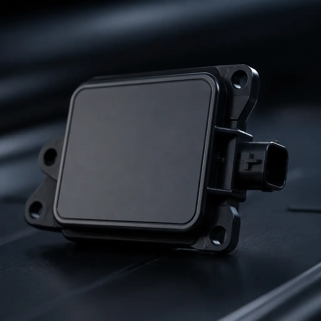
Automotive radar has become a backbone of modern ADAS, adaptive cruise control, automatic emergency braking, blind-spot detection and parking assistance all rely on a millimetre-wave sensor bolted in the bumper or behind the grille. Those sensors operate at 24 GHz, 77 GHz and now up to 81 GHz, and they are among the highest-frequency, most tolerance-sensitive PCB designs in mass production.
At those frequencies the PCB is no longer a carrier for the circuit, it is part of the RF path. The antenna is a printed structure on the board, the feed lines are controlled-impedance waveguides, and the laminate's dielectric constant and loss directly set the sensor's range and resolution. Get the board right in the first place and the factory test is straightforward; get it wrong and the sensor is poor even before the signal processing gets a chance.
Why Radar Boards Are Different
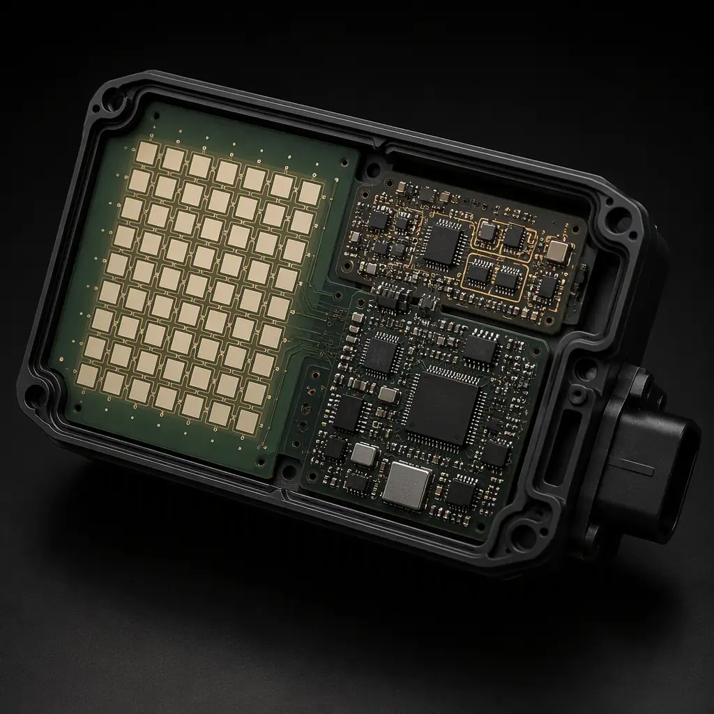
A radar front end is a mmWave microstrip design, and that changes the rules compared with a digital or power board. At 77 GHz the wavelength in a typical laminate is only a few millimetres, so the copper features are physically small and the tolerances are correspondingly tight.
The Board Is The Antenna
The transmit and receive antennas are printed patch arrays on the top copper layer, fed by a network of microstrip lines. Their resonant length depends on the laminate's dielectric constant, so a slight change in that constant shifts the centre frequency and spoils the radiation pattern. See our antenna design guide.
It Is A Controlled-Impedance World
The feed network is designed for a specific characteristic impedance: often 50 Ω, set by the trace width, dielectric thickness and constant. At mmWave, the etch tolerance and the dielectric thickness control that impedance far more tightly than at 2 GHz. Our impedance control guide covers the fundamentals.
Choosing The RF Laminate
The material is the single largest decision in a radar design. It is a trade-off between electrical performance, cost and manufacturability, and your choice drives the stackup and the fabricator's process.
Low Dk And Low Df
Look for a low dielectric constant and, critically, a low loss tangent. A good mmWave laminate has a dielectric constant around 3.0–3.5 and a loss tangent well under 0.003 at 77 GHz, so the signal survives the trace without being absorbed. Higher loss means a shorter usable radar range.
A Stable, Repeatable Dk
What matters is not just the average dielectric constant, but how consistent it is across the sheet and across lots. A stable Dk keeps the antenna tuned and lets the fabricator hold impedance without constant re-tuning. See our PTFE / high-frequency guide and RF PCB manufacturing guide.
Mixed Material For Cost Control
Many radar boards use a hybrid stackup: a high-performance RF laminate only in the antenna and front-end layers, with a standard FR-4 or a cheaper low-loss material for the digital back-end where the signal is down-converted and processed. This trims cost where the RF performance is not needed.
| Material class | Typical Dk | Loss tangent | When to use |
|---|---|---|---|
| General FR-4 | ~4.2 | > 0.02 | Not suitable for RF front end |
| Mid-loss FR-4 | ~3.6 | ~0.010 | IF / baseband layers |
| Low-loss RF (PTFE-based) | 3.0–3.5 | < 0.003 | Antenna & mmWave feed |
Stackup And Construction
A mmWave radar board is built around a carefully designed stackup, because the impedance and the radiation are set by the layer arrangement, not just the trace widths. Getting the dielectric thickness right is as important as the material choice.
Put The RF On The Top, The Control Below
The transmit and receive patch antennas and the MMICs live on the top copper; the digital processing and power plane sit lower down. A thick ground plane between the RF section and the radar processing keeps the two from interfering and provides the return path the antenna needs.
Control The Dielectric Thickness
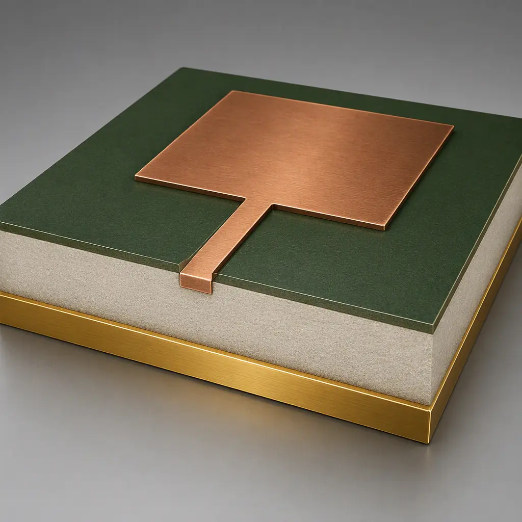
Microstrip impedance depends on the thickness of the dielectric between the top copper and the ground plane. A tight thickness tolerance is essential, because a variation here shifts the impedance and de-tunes the feed network. This is where a fabricator with a well-controlled lamination process earns its keep.
Avoid Signal-Gaps In The Reference
The ground plane directly under the RF traces must be continuous. Slots, splits or a plane cut up by vias in the RF region change the return path and the impedance, which is a common cause of a radar board that works in simulation but fails in the field. Keep the RF reference plane solid.
Etching Tolerance Is Everything
At 77 GHz, a trace-width change of a few tens of microns moves the impedance enough to matter. The fabricator's ability to hold a tight copper etch tolerance, and to keep it consistent across the full panel, is the practical difference between a sensor that meets spec and one that does not.
Specify A Tight Trace Tolerance
For a mmWave design, ask for a trace-width tolerance of around ±0.025 mm or better, and confirm the fabricator can hold it across the panel. A wider tolerance is acceptable for a digital trace but not for an antenna feed.
Validate With A Cross-Section
A cross-section check of the etched traces and the dielectric thickness verifies the actual, not the theoretical, dimensions. This is the concrete evidence that the board meets the impedance target. See our cross-section report guide and manufacturing tolerances guide.
Watch Copper Roughness At High Frequency
The surface roughness of your copper foil adds loss, especially at mmWave. A smoother foil (like a low-profile copper) has less conductor loss than a standard rough foil. For the antenna and feed layers this is a measurable performance factor, not a cosmetic one.
MMIC And Automotive Reliability
An automotive radar is a safety-critical component, so it is built and qualified to automotive standards. The board and the assembly have to survive the vibration, temperature and electrical stress of a car's lifetime, and they are usually second-sourced from more than one supplier.
Integrate The MMIC Cleanly
The radar MMIC is a small, high-frequency die or package, often sitting on the same board as the antenna. Its grounding and its RF interconnect must be clean, with a low-inductance path to the ground plane and short feed connections. The solder joint on an mmWave part is electrically critical, so the assembly process has to be precise.
Build To Automotive Quality
Automotive electronics are built to a strict quality system, IATF 16949, PPAP and AEC-Q requirements, with lot traceability and a documented process. Our automotive PCB requirements guide and PPAP guide detail what a compliance package should contain.
Dual-Source To Manage Supply Risk
An automotive sensor is a long-lived, high-volume part, and a single-source laminate or fabricator is a real risk. Our dual-sourcing strategy and supplier transition guide cover how to qualify a second source without changing the performance.
Summary, The Fabricator Is Part Of The Design
An automotive radar board is designed for a specific laminate, a controlled stackup, tight etch tolerance and a careful RF layout. None of that is a black box you can hand to a generic fabricator. Choose a low-loss RF laminate, hold the dielectric thickness and etch tolerance, keep the ground plane solid and integrate the antenna and MMIC cleanly, and work with a supplier that can demonstrate it with cross-sections and a documented automotive quality system.
At Huaxing PCBA we manufacture high-frequency RF boards including PTFE and hybrid stackups on 8 SMT lines, and we support IATF 16949 and PPAP documentation with full lot traceability. Our engineers can review your stackup and etch tolerances before we quote. Send your Gerber and BOM or talk to an RF engineer about your radar front-end.
