
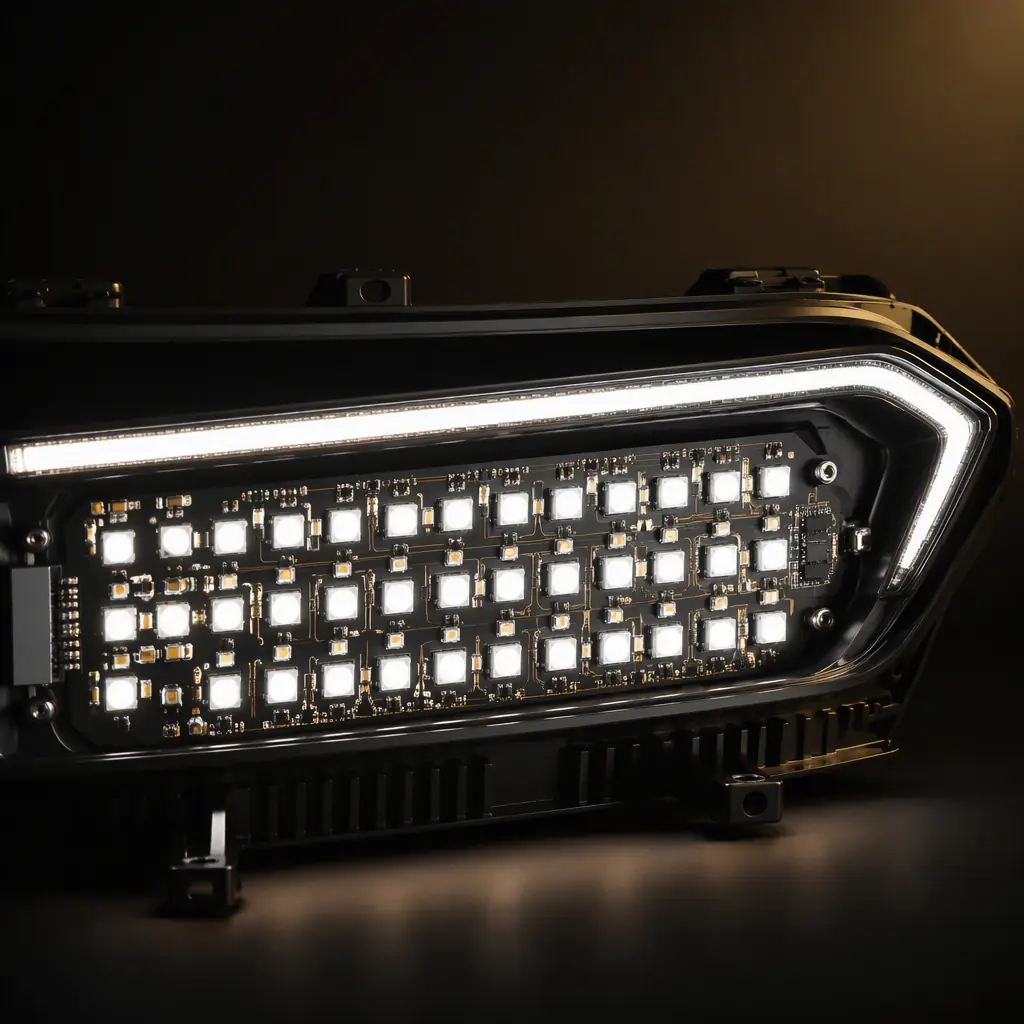
Automotive lighting has moved from simple bulb-and-reflector systems to dense electronic modules: matrix LED headlamps with 100+ individually addressable LEDs, adaptive driving beam (ADB) systems that steer light around oncoming traffic, and rear combination lamps with animated light sequences. Every one of those functions lives on a PCB that must survive ambient temperatures up to 105-125°C, constant vibration, humidity cycling, and EMC environments that would cripple a consumer board. This guide covers the design decisions that determine whether an automotive lighting PCB survives in the field, or fails inside the warranty period.
Automotive lighting is one of the fastest-growing segments in vehicle electronics: the global market is projected to pass $45 billion by 2030, driven by LED adoption, ADB regulation changes, and the transition to electric vehicles. We manufacture automotive PCBs and PCBA under IATF 16949 across 8 SMT lines in Shenzhen, and the rules below are the ones our automotive customers' boards actually follow. Start with our automotive PCB requirements guide for the overall qualification picture, then come back here for lighting-specific depth.
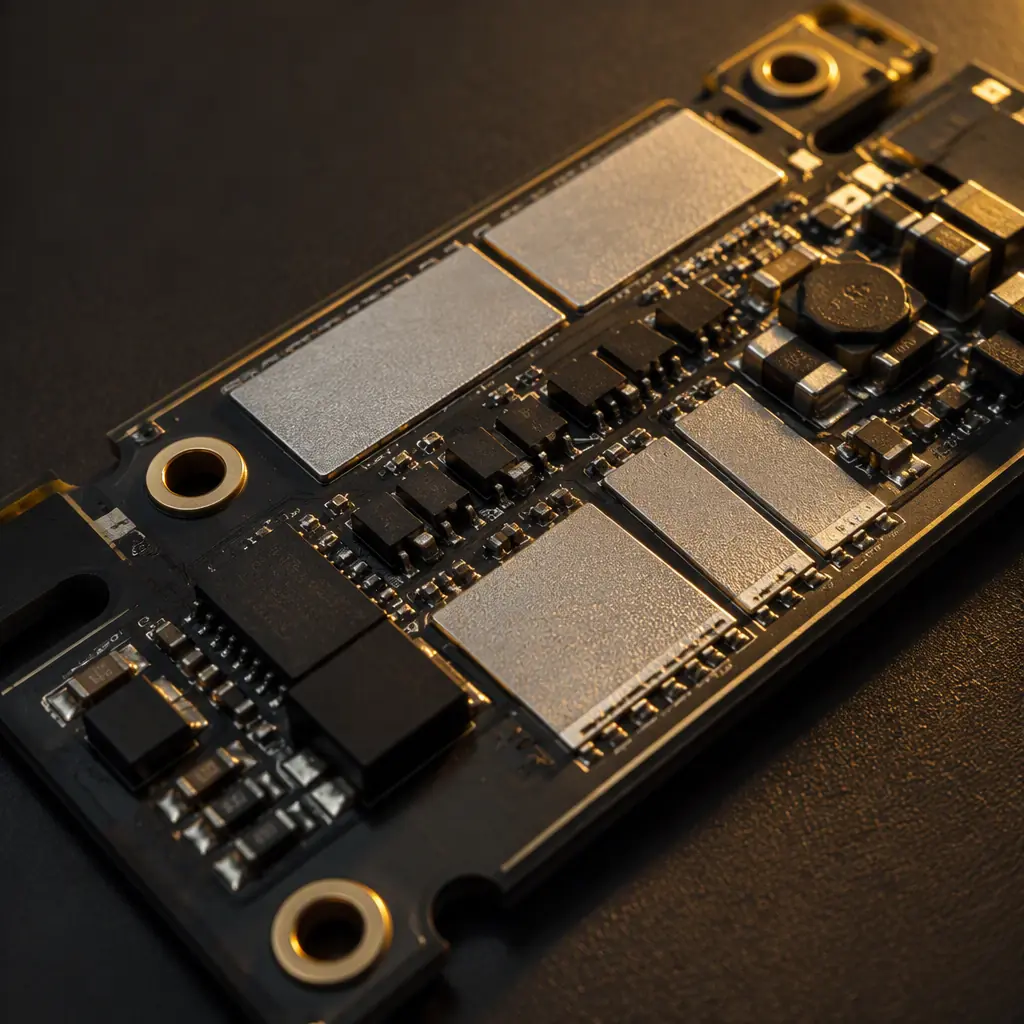
Why Lighting PCBs Are Different From Other Automotive Boards
Every automotive PCB must handle vibration, temperature, and EMC. Lighting boards add three specific challenges that push them beyond typical ECU boards:
Localized heat density, not just ambient heat
A headlamp driver board may draw 50-100 W, with the LED array concentrated in a small area. Junction temperatures of 150°C are common at the LED die, and the board must conduct that heat away faster than it arrives. This is why thermal design, not logic design, dominates lighting PCB layout. For the fundamentals of moving heat off the board, see our thermal management guide.
Mixed power and control on one board
Lighting modules combine high-current switching regulators (3-10 A per channel), sensitive microcontroller control, and CAN/LIN communication, all within centimeters. The switching loops of buck converters are the classic EMI source, and they sit right next to the communication lines that must stay clean. Our power integrity guide covers the layout discipline this requires.
Sealed, unserviceable housings
Headlamp assemblies are sealed against moisture and typically not serviceable. The whole unit is replaced if an LED driver fails. There is no field repair, so the PCB must be designed for the full vehicle lifetime, which OEMs usually spec at 10-15 years. This drives everything from component derating to conformal coating to solder joint reliability.
Key Takeaway: In automotive lighting, thermal management and EMC are not "nice to have", they are the product. A driver board that runs 20°C cooler or emits 6 dB less noise is worth more to an OEM than one with fancier features.
Board Construction: Substrate, Copper, and Stackup Choices
The first decision is the base material, and for high-power lighting there are really two standard answers:
Aluminum-core (IMS) boards for high-power LED arrays
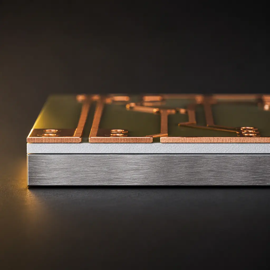
Insulated metal substrate (IMS) boards use a thin dielectric layer over an aluminum base, giving thermal conductivity of 1-3 W/m·K through the dielectric versus 0.3 W/m·K for standard FR-4. For LED arrays dissipating more than ~2 W per LED, an IMS board is usually the right call. The tradeoff: IMS boards are single-sided for practical purposes and harder to route. Our metal core PCB guide covers the full material comparison.
High-Tg FR-4 with thick copper for driver electronics
The driver electronics (buck converters, MCU, CAN transceiver) typically live on a standard multilayer FR-4 board with high-Tg laminate (170°C+) and 2-3 oz copper on power layers. Splitting the LED array (IMS) from the driver (FR-4) into separate boards connected by a short harness is a common architecture that keeps both boards simple.
Copper weight selection is a thermal decision
Trace resistance at 5-10 A is not just an electrical loss, it is heat generated inside the board. A 1 oz trace carrying 8 A drops significant voltage and heats up; moving to 2-3 oz copper on the power paths cuts both. For the current-carrying math, see our copper weight selection guide . The IPC-2152 charts are the ones your CM will use.
For ADB modules with 100+ LEDs, a hybrid approach is emerging: IMS substrate with multiple parallel driver channels, or double-sided IMS with the driver on the front and LEDs on the back. Whatever the stackup, the thermal path must be verified with simulation before layout. A 1 mm² LED pad with a missing thermal via array can be the difference between a 90°C and a 130°C junction temperature.
Thermal Design: Vias, Pads, and the Heat Path
Heat in a lighting board moves in three directions: down through the LED pad into the substrate, laterally through copper planes, and up through the LED's own thermal pad. The designer's job is to make all three paths as short and wide as possible.
| Design Element | Rule of Thumb | Why |
|---|---|---|
| LED thermal pad area | ≥ 2× LED die footprint | Spreads heat before it enters the substrate |
| Thermal vias under LED | 12-24 vias per LED, 0.3-0.5 mm | Each via adds a parallel conduction path to the aluminum base |
| Via tenting | Fill or tent vias in LED zones | Prevents solder wicking away from the LED pad during reflow |
| Copper pour on LED layer | Maximum pour, no ground plane splits | Lateral spreading reduces hot spots between LEDs |
| Dielectric thickness (IMS) | 35-100 µm, thinner = better conduction | Thinner dielectric conducts heat faster but raises capacitance to the base |
| Junction temperature target | ≤ 125°C at worst-case ambient | Keeps LED lifetime above 50,000 hours |
One subtlety that catches designers: solder paste coverage on the LED thermal pad. A typical LED thermal pad has a large solid copper area, and 100% paste coverage can cause voiding and floating. Most lighting modules use a stencil with 50-70% coverage in a checkerboard or perimeter pattern on the thermal pad, see our solder paste guide and reflow profile optimization guide for the process side of this equation.
EMC: Keeping the Switching Noise Out of the CAN Bus
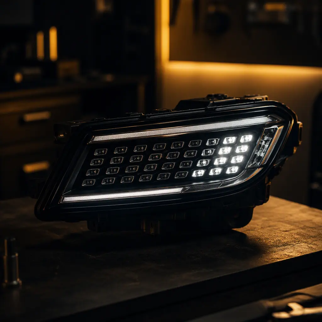
Lighting modules are notorious EMI offenders because they combine high-frequency switching regulators with long harnesses that act as antennas. The layout rules that matter most:
Minimize the high-frequency switching loop
The loop formed by the high-side FET, inductor, and catch diode carries the highest di/dt in the module. Keep this loop physically small, components as close as possible, return path directly underneath. Every extra millimeter of loop area adds radiated emissions. Our EMI/EMC design guide has the full loop-area analysis.
Separate power and communication ground returns
Switching currents must not flow through the MCU or CAN transceiver ground returns. A star ground or split ground plane with a single tie point at the connector keeps the noisy return path away from the sensitive circuitry. This matters even on 2-layer boards. The ground pour should be continuous under all switching components.
Filter the connector interface
Common-mode chokes on the CAN/LIN lines, ferrite beads on the battery input, and TVS diodes on every pin that leaves the housing. Automotive transients (ISO 7637-2) can exceed 100 V on the supply line. The input filter is the module's first line of defense. Our ESD control guide covers the protection components and their placement.
If your lighting module will be certified against CISPR 25 (the automotive emissions standard), plan for radiated emissions testing from the first layout review. Retro-fitting EMI filters after a failed test costs more and performs worse than designing them in from the start.
Manufacturing and Reliability Requirements Under IATF 16949
Designing the board is half the battle. Manufacturing it to automotive standards is the other half. Lighting modules are high-volume, high-reliability parts, and OEMs typically require:
IATF 16949 certified manufacturing
Every automotive PCB supplier should hold IATF 16949. The automotive quality management standard that adds APQP, PPAP, and special process control on top of ISO 9001. If your CM is not IATF 16949 certified, your OEM customer will reject them at audit. See our certifications guide for how to verify a certificate is real.
IPC-A-610 Class 3 acceptance with 100% AOI + X-ray
Lighting boards with 0201 passives and fine-pitch LED drivers need Class 3 inspection criteria. AOI catches placement defects; X-ray verifies BGA and QFN solder joints that AOI cannot see. Our inspection guide explains the full machine inspection chain.
Thermal cycling and vibration qualification
Expect to qualify the assembled module with thermal cycling (-40°C to +125°C), thermal shock, random vibration, and damp heat. The PCB design decisions above, via fill, copper weight, solder joint geometry, are exactly what these tests validate. Our thermal cycling testing guide and vibration testing guide detail the test profiles and pass criteria.
Conformal coating for the unsealed reality
Even "sealed" headlamp housings see condensation. A thin acrylic or silicone conformal coating on the driver board side protects against moisture and ionic contamination. The coating must not cover the LED thermal pads or connector pins, selective coating is standard. Our conformal coating guide covers material selection and application methods.
Summary: The Lighting PCB Design Checklist
Before you send a lighting module to manufacturing, verify every line of this checklist:
| Category | Checklist Item |
|---|---|
| Thermal | LED junction ≤ 125°C at worst case; thermal via array sized to power; IMS or high-Tg substrate selected for heat load |
| Power | 2-3 oz copper on high-current paths; switching loop minimized; input filter with TVS on all external pins |
| EMC | Power/comm ground separation; CISPR 25 planned from layout; common-mode chokes on CAN/LIN |
| Reliability | IPC-A-610 Class 3 criteria; X-ray on all BGA/QFN; thermal cycling + vibration qualification planned |
| Manufacturing | IATF 16949 CM; PPAP documentation; 100% AOI; solder paste coverage ≤70% on LED thermal pads |
At Huaxing PCBA, we build automotive lighting PCBs under IATF 16949 with 8 SMT lines, X-ray and AOI inspection on every board, and thermal cycling capability in-house. If you are designing a headlamp driver, ADB module, or rear-lamp board, send us your design for a DFM review. We will flag the thermal and EMC risks before they cost you a qualification cycle. Contact our automotive team, or read our ADAS PCB guide for the adjacent electronics that share the same vehicle environment.
