
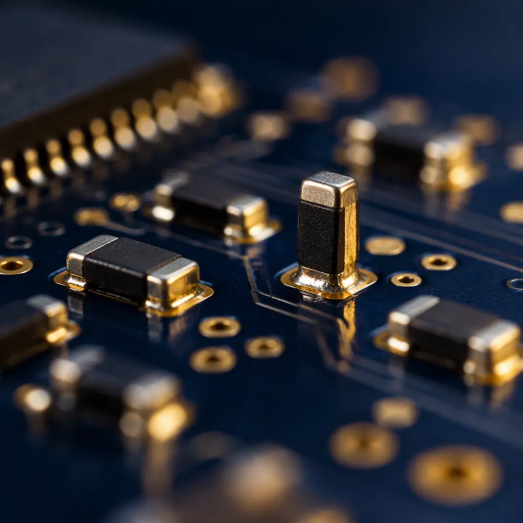
A finished board that passes AOI and 2D X-ray is not automatically a board with good solder joints. Two defect modes — tombstoning and head-in-pillow — sit in exactly the blind spot that 2D transmission X-ray cannot resolve, and both are caused by forces and dimensional changes that happen while the solder is molten, not after. If your acceptance process ends at "X-ray looks clean," you are accepting both risk classes without measuring them.
This guide separates the two mechanisms (they are routinely conflated), gives the numeric triggers behind each, and closes with the process controls a buyer should expect a contract manufacturer to be able to demonstrate. At Huaxing PCBA we run 8 SMT lines with SPI, AOI and 3D CT capability in-house, which matters here because one of these two defects is only reliably caught by the third of those tools.
Why 2D X-Ray Cannot See Either Defect
Transmission X-ray produces a two-dimensional shadow. Its contrast comes from how much material the beam passes through. That geometry works well for voids (a void removes material) and for bridging (a bridge adds material in a place that should be empty).
Neither of these defects produces a clean material contrast change in the shadow image. A tombstoned part is fully separated from one pad — but the body of the component itself sits in the beam path above that pad, so the shadow still shows a component-shaped mass where the joint should be. A head-in-pillow joint has the ball and the paste both present and both within a fraction of a millimetre of each other; the beam integrates them into one apparent joint.
Key Takeaway: Both defects are geometric failures in the vertical axis. 2D X-ray collapses the vertical axis. That is not a resolution problem you can solve by buying a sharper machine — you need 3D CT, cross-sectioning, or a destructive technique.
Tombstoning — A Force Balance Problem
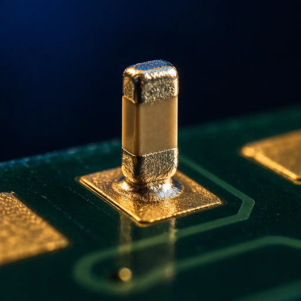
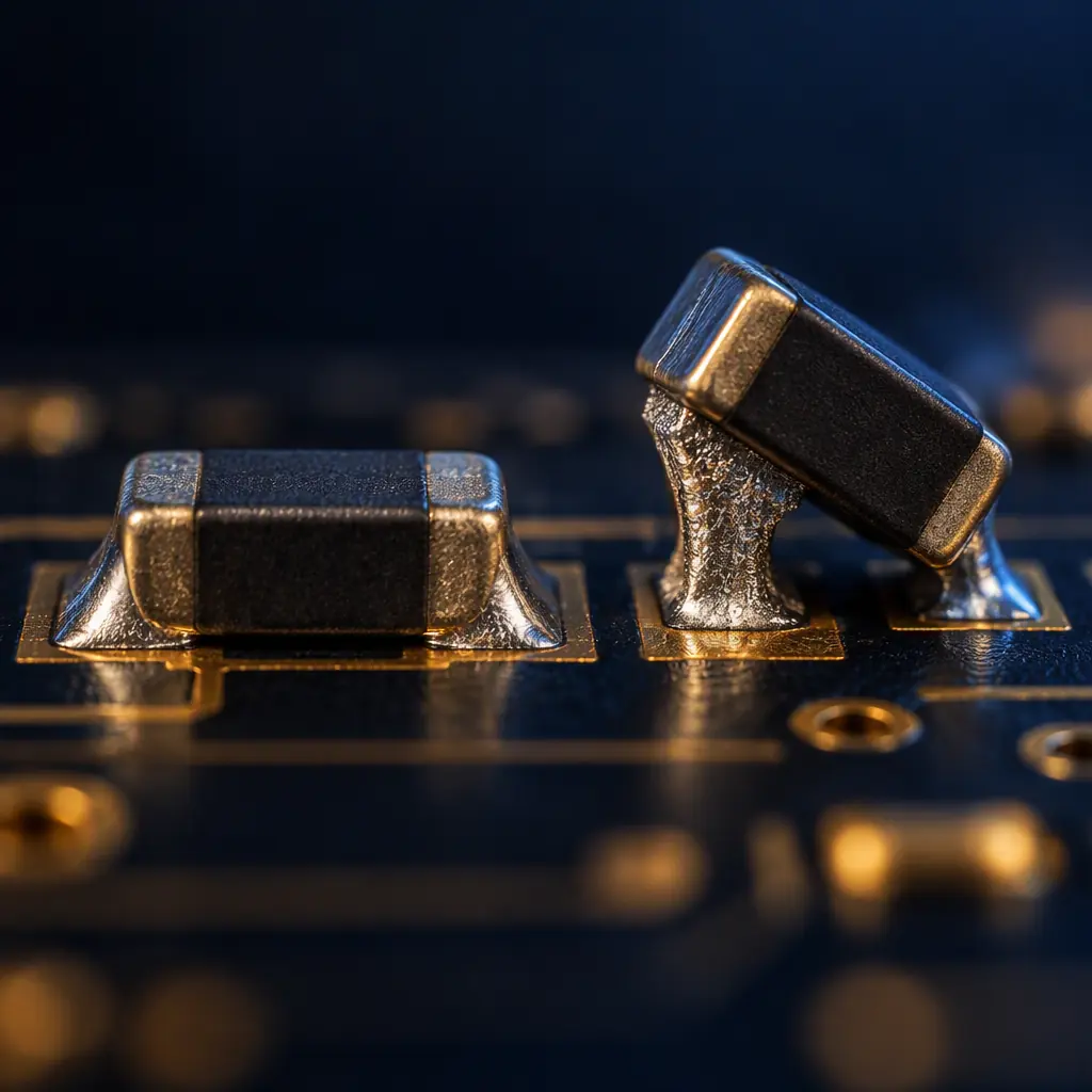
Tombstoning (also called the Manhattan effect or drawbridging) happens when one end of a two-terminal chip component lifts free of its pad during reflow and stays lifted after solidification. The component ends up standing on one end like a headstone.
The mechanism is a moment balance. While the solder is liquid, four forces act on the component: the surface tension of the molten fillet at each end, the tack force of the paste holding the part down, gravity, and the hydrostatic lift from any volatiles escaping the paste. Tombstoning occurs when the net moment about one termination exceeds what the other end can resist.
Because the imbalance is a moment, the two most common root causes are both asymmetries: unequal solder volumes at the two ends, and unequal heating rates at the two ends.
Pad Geometry: The 1:1.1 Rule
The single most common design driver is pad width relative to component termination width. When the pad is exactly the same width as the termination (a 1:1 ratio), the molten fillet has no room to form a concave, outward-pulling shape and instead tends to pull the termination toward the pad centre, contributing to lift. Extending the pad width so it is roughly 10 percent wider than the termination — a 1:1.1 ratio — gives the fillet a stable outward curvature and measurably reduces the lift moment. Pad width and footprint density choices are covered in more depth in our guide to IPC-7351 land pattern density levels.
Paste Volume Imbalance
If one pad receives more paste than the other — through a partially clogged aperture, a stretched stencil, or a stencil not properly seated — the tack force is unequal and the fillet sizes that form are unequal. A 15 percent volume difference between the two apertures of a single 0402 footprint is enough to shift the balance on a light part. This is why SPI volume control belongs upstream of any tombstoning investigation: the defect is often decided before the board reaches the reflow oven.
Thermal Mass Asymmetry
If one pad is connected to a ground plane or a heavy copper pour and the other is connected to a thin signal trace, the two ends do not reach liquidus at the same time. The early-melting side wets and pulls while the late side is still solid, and the resulting imbalance can flip a small part. A useful design target is to keep the temperature difference across a component's pads within about 5°C during ramp. Where that is impossible, thermal relief spokes or a longer soak can compensate.
Reflow Profile: Soak vs Spike
A profile that ramps too fast to peak gives the flux less time to activate and the two ends less time to equalise in temperature. A soak phase that holds the board above flux-activation temperature but below liquidus for 60-120 seconds lets the thermal mass of the assembly equalise before the solder melts, which directly addresses the asymmetry mechanism. Profile structure is covered in our guide to reflow profile optimisation, and the oxygen side of the same question is in our article on nitrogen reflow and O2 control.
Component Part Size and Body Mass
The lighter the component, the smaller the restoring moment from gravity. This is why the defect is most commonly seen on 0402 and 0201 passives and on small diodes and LEDs, and why it is rare on 1206 or larger bodies. The handling and stencil consequences of very small parts are covered in our guide to fine-pitch SMT assembly.
Head-in-Pillow — When the Ball Never Met the Paste
Head-in-pillow (HIP) is a different failure and gets far less dedicated treatment than it deserves, because it is routinely lumped in with tombstoning as a "reflow defect." The mechanism is unrelated.
In a BGA or CSP assembly, solder spheres are already attached to the package, and solder paste is printed onto the board pads. During reflow, the paste must coalesce with the sphere. In a head-in-pillow defect, the paste melts and forms a rounded dome, and the sphere contacts that dome but the oxide films on the two surfaces never break through and merge. The result is a joint that is physically touching but not metallurgically continuous.
The Driver Is Dynamic Package Warpage
The package substrate warps as it heats. A ball-grid package that is flat at room temperature can bow by tens of microns at reflow temperature, lifting the centre balls upward relative to the board. Where the gap opens beyond what the paste column can bridge, the two surfaces separate at the moment they should be merging. The relevant measurement is dynamic warpage at peak temperature, specified in JESD22-B112, not the room-temperature coplanarity figure that appears on most datasheets.
Why It Survives X-Ray and AOI
The ball is in the correct place. The paste is in the correct place. The package is in the correct place. There is no void to show as a dark spot and no bridge to show as extra material. In a 3D CT slice the separation may appear as a thin horizontal void at the ball-to-paste interface, but in a 2D transmission image the two masses integrate. This is why HIP is the classic escapee in facilities whose final verification is AOI plus 2D X-ray only.
Detection That Actually Works
Three techniques reliably find HIP. 3D computed tomography resolves the interface in the vertical plane. Cross-sectioning with a microsection shows the unmet interface directly, and interpreting those images is the subject of our guide to microsection analysis. Dye-and-pry, in which the assembly is immersed in dye then mechanically separated, stains every open interface and is the standard forensic confirmation. A process that lists X-ray but not one of these three as its HIP detection method is not actually measuring for HIP.
Prevention Levers
Four levers reduce HIP incidence: a slower soak and a longer time above liquidus so paste and ball have time to merge; sufficient paste volume so the column can bridge the warped gap; lower-oxygen atmosphere to reduce oxide formation at the interface, which is the same O2 control discussed in our nitrogen reflow guide; and a verified package warpage specification agreed with the component supplier before the assembly is qualified. For packages with an exposed thermal pad, voiding and paste coverage interact with the same levers, as covered in our guide to QFN and LGA leadless package soldering.
Symptom → Cause → Fix, Side by Side
The two defects are easy to confuse at the symptom level, and confusing them wastes a reflow-profile experiment on what is really a package or stencil problem. This table maps what you observe to what is actually happening.
| Observed Symptom | Defect | Primary Cause | First Corrective Action |
|---|---|---|---|
| Two-terminal part standing on one end | Tombstoning | Paste volume or thermal asymmetry across the pad pair | Check SPI volume matching; widen pad to 1:1.1 |
| Part lifted, both fillets present but one end open | Tombstoning | Insufficient tack force on lifted end | Extend soak; verify aperture not partially clogged |
| BGA passes AOI and 2D X-ray, fails at functional test | Head-in-pillow | Dynamic package warpage exceeded paste bridging capacity | Increase paste volume; extend time above liquidus |
| Intermittent open that appears after thermal cycling | Head-in-pillow | Non-metallurgical contact degraded by CTE mismatch | Dye-and-pry to confirm; requalify package warpage |
| Centre balls of a large BGA worst affected | Head-in-pillow | Maximum warpage occurs at package centre | Reduce O2 ppm; review package coplanarity at reflow temp |
| Defect count varies with component supplier lot | Either | Dimensional variance between supplier lots | Add incoming dimensional and warpage check |
For broader coverage of the other joint-level defect families — voids, bridging and cold joints — see our dedicated article on PCB solder joint defects, which covers the modes that 2D X-ray and AOI do catch reliably.
What to Demand From Your PCBA Supplier
Both defects are process-discipline problems, and process discipline is auditable. Five questions separate a supplier that genuinely controls for these modes from one that simply owns an X-ray machine.
Which detection method do you use for head-in-pillow?
A correct answer names 3D CT, cross-section or dye-and-pry. An answer of "X-ray" indicates the defect is not being measured at all. Ask to see a sample CT slice or microsection of a ball array from a production lot.
Do you have SPI upstream of reflow, and what is the volume Cpk?
Tombstoning prevention depends on paste volume matching across a footprint. SPI data is the objective evidence. Our article on solder paste volume control covers the Cpk targets worth asking for.
Is the reflow profile board-specific or a house default?
An assembly with heavy copper and one with thin traces need different soak structures. A supplier running a single default profile across all products cannot be controlling thermal asymmetry. Ask for the profile for your specific stackup.
Do you verify package dynamic warpage before qualifying a new BGA?
The relevant figure is warpage at reflow temperature per JESD22-B112, not dat-asheet coplanarity. A supplier that qualifies a new package on the basis of room-temperature coplanarity is leaving the HIP mechanism unaddressed.
How are these defects reflected in your DPPM and returns data?
If HIP is not a defect code in the supplier's quality system, it will not appear in the data. The metrics worth reviewing are covered in our guide to PCB quality metrics and DPPM benchmarks, and the inspection sampling that supports them in our article on AQL sampling plans.
Procurement Tip: When you audit a new assembly partner for high-reliability work, ask for one artifact: a dye-and-pry report or a 3D CT slice of a production BGA. If neither exists, you have found the boundary of their process control before you have placed an order.
Summary
Tombstoning and head-in-pillow share a symptom category — a joint that looks present but is not electrically reliable — and almost nothing else. Tombstoning is a force-balance failure driven by paste volume and thermal asymmetry across a two-terminal footprint, and it is largely preventable at the design and printing stages. Head-in-pillow is a dynamic warpage failure in ball-grid packages, it is invisible to 2D X-ray by construction, and controlling it requires both the right reflow atmosphere and a detection method that actually resolves the vertical interface.
The practical consequence for a buyer is that "X-ray passed" is not a sufficient acceptance statement for either mode. Ask which specific technique covers HIP, and treat the answer as a direct read on how well the supplier's process is instrumented.
At Huaxing PCBA, we build assemblies across IPC Class 2 and Class 3 with in-house SPI, AOI, 3D CT and microsection capability, and we run board-specific reflow profiles rather than a house default. Our process engineering team reviews footprint geometry and package warpage risk at DFM stage, before tooling exists. Review our guide to IPC Class 2 versus Class 3 or contact our engineering team for a project-specific review of your assembly's defect risk.
