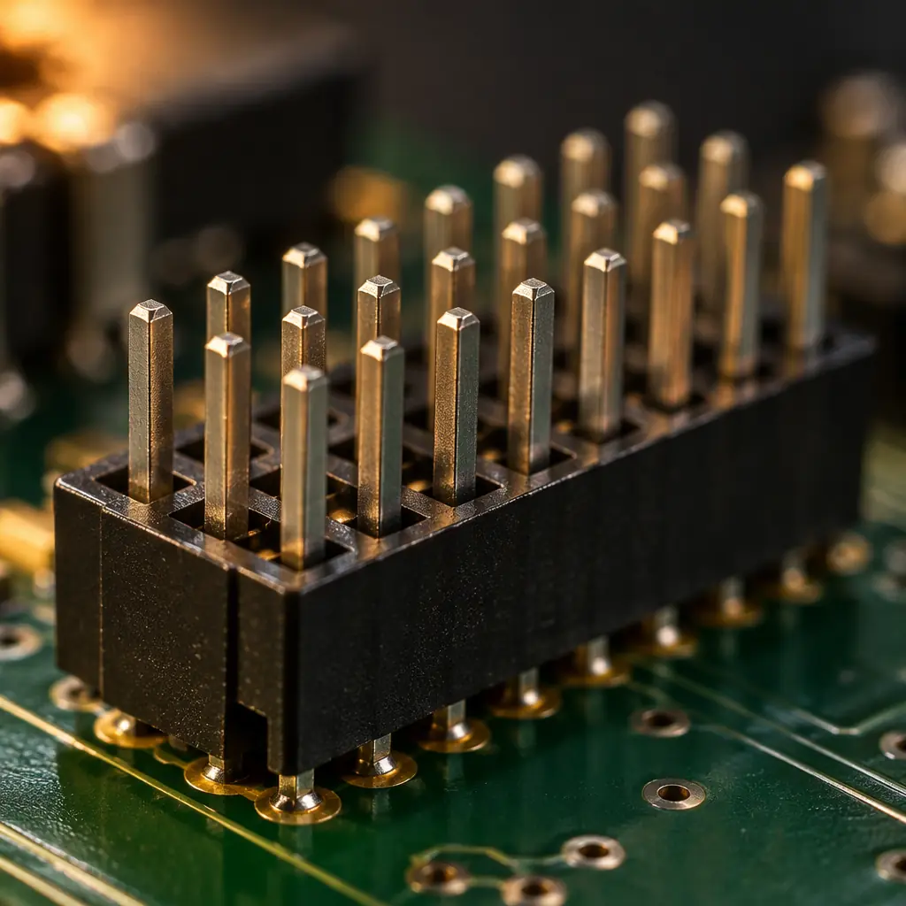
A connector is the only component on most assemblies that a human will touch repeatedly, and it is also the one most often attached by the least examined process on the line. Teams will spend a week on a BGA reflow profile and then specify a 96-pin backplane connector the same way they specified it in 2015. The three available methods differ by roughly a factor of four in per-pin cost at low volume, and they trade entirely different defects against each other.
The decision is not primarily about quality. All three methods produce reliable joints when the process window is respected. It is about which process window your board can actually hold, and how much rework you are prepared to do when it cannot. A press-fit design that ships with a hole tolerance the fabricator cannot maintain is worse than a soldered design, because the failure is a loose pin in the field rather than a visible solder defect at final inspection.
The Three Methods and What Each One Is For
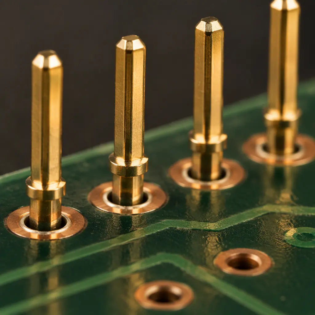
Press-fit drives an eye-of-the-needle pin into a plated hole and relies on elastic springback of the pin's compliant section to hold it against the barrel wall. There is no metallurgical bond, so there is no solder joint to inspect and no thermal excursion. The pin can be replaced, which is why press-fit dominates backplane and telecom equipment where a 2,000 pin connector must be repairable.
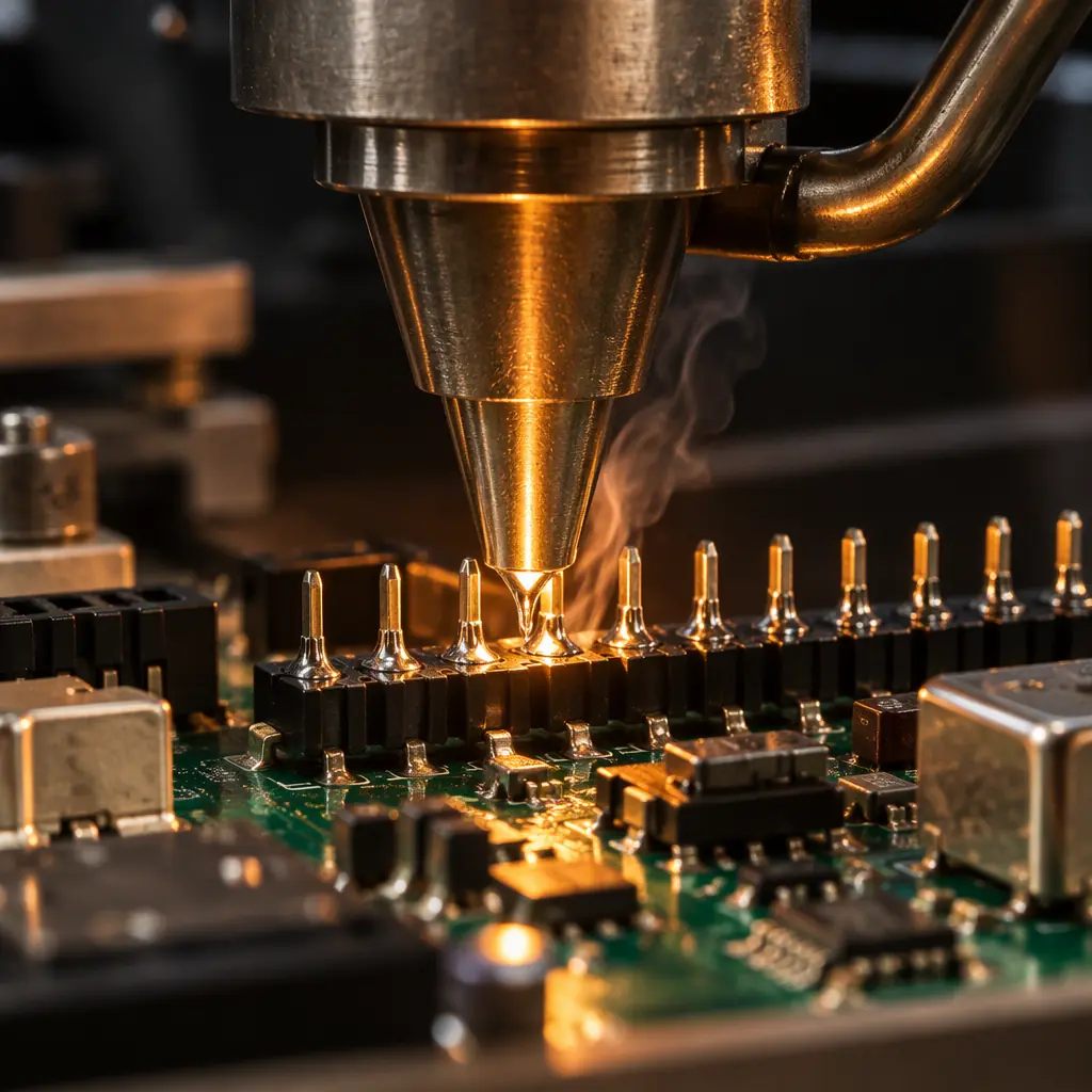
Selective soldering floods one nozzle or one mini-wave over the pins of a single connector while the rest of the board is masked or shielded from the heat. It is the workhorse for mixed-technology boards with 10 to 300 through-hole pins, and it handles connectors that cannot survive a reflow oven, either because the housing is not high-temperature rated or because the pin volume is too large for paste.
Pin-in-paste prints solder paste into the hole and around the pin and lets the reflow oven do the work. Its attraction is that it removes an entire process step: no wave, no selective machine, no second pass. Its limit is paste volume, which scales with hole diameter and pin geometry and cannot be increased indefinitely without creating voids or bridging. The pin-in-paste process guide covers the volume calculations in detail.
Cost per Pin: Where the Crossover Sits
The numbers below come from our own line cost model for a board with a single connector of the stated pin count, medium volume of 500 to 2,000 boards per month, excluding the connector itself. Treat them as the shape of the curve rather than a quotation; the crossover point is what matters.
| Method | Setup and tooling | Cost per pin (volume) | Break-even against selective solder |
|---|---|---|---|
| Selective solder | USD 150 to 400 programming and fixture | USD 0.010 to 0.018 | Baseline |
| Pin-in-paste | USD 0 (uses existing stencil and reflow) | USD 0.004 to 0.009 | Immediate, when the connector qualifies |
| Press-fit, manual arbor press | USD 800 to 2,500 tooling | USD 0.030 to 0.060 | Rarely wins on cost alone |
| Press-fit, automated insertion | USD 6,000 to 15,000 tooling | USD 0.008 to 0.014 | Around 20,000 pins per year |
The pattern is straightforward. Pin-in-paste is the cheapest method whenever the connector can take it, because the marginal cost is paste volume and oven capacity that is already paid for. Press-fit only becomes competitive at enough annual pins to amortise tooling, and manual press-fit essentially never competes on cost, existing for repair and prototype work. Selective solder sits in the middle and wins on applicability rather than price.
The hidden cost line is rework. A bridged selective solder joint costs a touch-up, roughly 30 to 60 seconds of a skilled operator's time. A press-fit pin that fails pull-force test requires the connector to be pressed out, the hole to be inspected and possibly re-plated, and a new connector pressed in. Our rework and repair guide sets out the limits on how many times a plated hole can be reworked before the barrel is compromised, which for press-fit is generally once.
Hole Tolerance: The Requirement That Kills Press-Fit Programs
Press-fit is a mechanical interference fit, so the finished hole diameter becomes a functional dimension rather than a manufacturing detail. The compliant section deflects by a defined amount and generates a defined normal force against the barrel. If the hole is 0.05 mm oversized, the normal force drops, retention force falls with it, and the connection becomes susceptible to fretting corrosion under vibration. If the hole is 0.05 mm undersized, insertion force rises sharply and the risk becomes barrel damage and board flex during pressing.
Typical eye-of-the-needle specifications call for a finished hole of 1.00 mm plus or minus 0.05 mm for a nominal 0.6 mm square pin, with a drill and plating capability that holds Cpk of at least 1.33 on that dimension. That is achievable, but it is a different order of process control than the plus or minus 0.10 mm that plenty of standard fabrication flows hold. Getting there means the fabricator must control drill wear, plating thickness and reflow shrinkage of the laminate as a system, and it must measure finished hole diameter rather than drill diameter.
Retention force is the acceptance test that closes the loop. The retention and pull-force specification page covers the test method and the numbers to require per pin size. What buyers miss is sample size: pull testing is destructive, so the specification needs to state how many pins per lot are tested and how many are permitted to be sacrificed, because a connector with 200 pins cannot lose 20 of them to testing.
Defects Each Method Trades For
Selective solder trades for thermal damage and bridging. The nozzle heats a local area to 250 to 280 degrees Celsius, and the connector housing must be rated above that. A housing rated to 240 degrees will deform subtly, enough to change the mating force, without any visible sign. Bridging between adjacent pins appears when the nozzle dwell is long enough for solder to flow across the gap, which is a programming problem, not a materials problem.
Pin-in-paste trades for voids and incomplete fill. Paste printed into a hole releases flux and solvent during reflow, and that gas must escape past the pin. If the hole is filled from one side only and the pin blocks the vent path, voiding above 25 percent of the barrel cross-section is common. The X-ray void acceptance criteria set the limits, and the process fix is usually a stencil aperture with a vent slot or a pin length that leaves a clear escape path.
Press-fit trades for hole damage and pin damage. Insertion with a misaligned tool bends the compliant section, which reduces normal force even if the pin appears seated. Board flex during pressing cracks the barrel at the knee where the plating meets the surface pad, and that crack is invisible without cross-sectioning. This is why press-fit programs live or die on the insertion tooling and the support fixture underneath, not on the pin specification. The press-fit assembly guide covers tooling and support in detail.
A Decision Sequence for Your Board
Start with the connector housing's temperature rating. Below 260 degrees, pin-in-paste and selective solder are both at risk and press-fit becomes the natural candidate. Above 260 degrees with fewer than 200 pins, pin-in-paste is the default and should be checked first for paste volume feasibility.
Second, count the pins and the annual volume. Above roughly 20,000 pins per year with a repairability requirement, automated press-fit earns its tooling. Below that, selective solder is almost always the right answer on cost, and it is the only one of the three that tolerates a wide hole tolerance without a functional consequence.
Third, ask whether the connector will ever be replaced in the field. If yes, press-fit moves up the list regardless of cost, because the alternative is field desoldering a 96-pin connector with a hot-air tool, which is a repair procedure most contract manufacturers will not warrant. Cable-side termination has its own inspection standard, covered in the IPC-A-620 harness inspection guide, and the same logic applies: define the acceptance criteria before the process, not after the first reject lot.
Finally, write the hole tolerance, the insertion force window, the pull-force sample plan and the rework limit into the purchase order. Every press-fit dispute we have mediated traced back to a drawing that specified a pin and a connector but never specified the hole it was going into.