You have committed to the coating in your specification, and the supplier tells you it is IPC-A-610 compliant. Then a batch of boards arrives and the coating peels off a component edge within a month of field operation. The reason is almost never a material problem, it is a conformance problem. IPC-A-610 sets out a specific, measurable set of acceptance criteria for conformal coating, and those criteria change sharply between Class 1, Class 2 and Class 3. Almost nobody writes them into the order, and almost nobody inspects them.
This matters because coating is one of the cheapest reliability investments on an assembly and one of the most poorly verified. At Huaxing PCBA, conformal coating runs through our 8 SMT lines with automated selective application and UV inspection on every board, and we quote coating to a documented 25–250 µm wet film range against a defined inspection level. This guide is the acceptance language you should be asking for.
What IPC-A-610 Actually Requires for Conformal Coating
IPC-A-610 is the worldwide acceptance standard for electronic assemblies, and it treats conformal coating as a specific workmanship requirement rather than a pass/fail afterthought. The relevant criteria are in the coating and conformal section, cross-referenced with IPC-CC-830 for material qualification and IPC-HDBK-830 for design. The acceptance rules break into five verifiable categories. Note that while our conformal coating selection guide covers material choice, this article is specifically about the acceptance criteria that decide whether a coated board is accepted or rejected.
Coating continuity and coverage
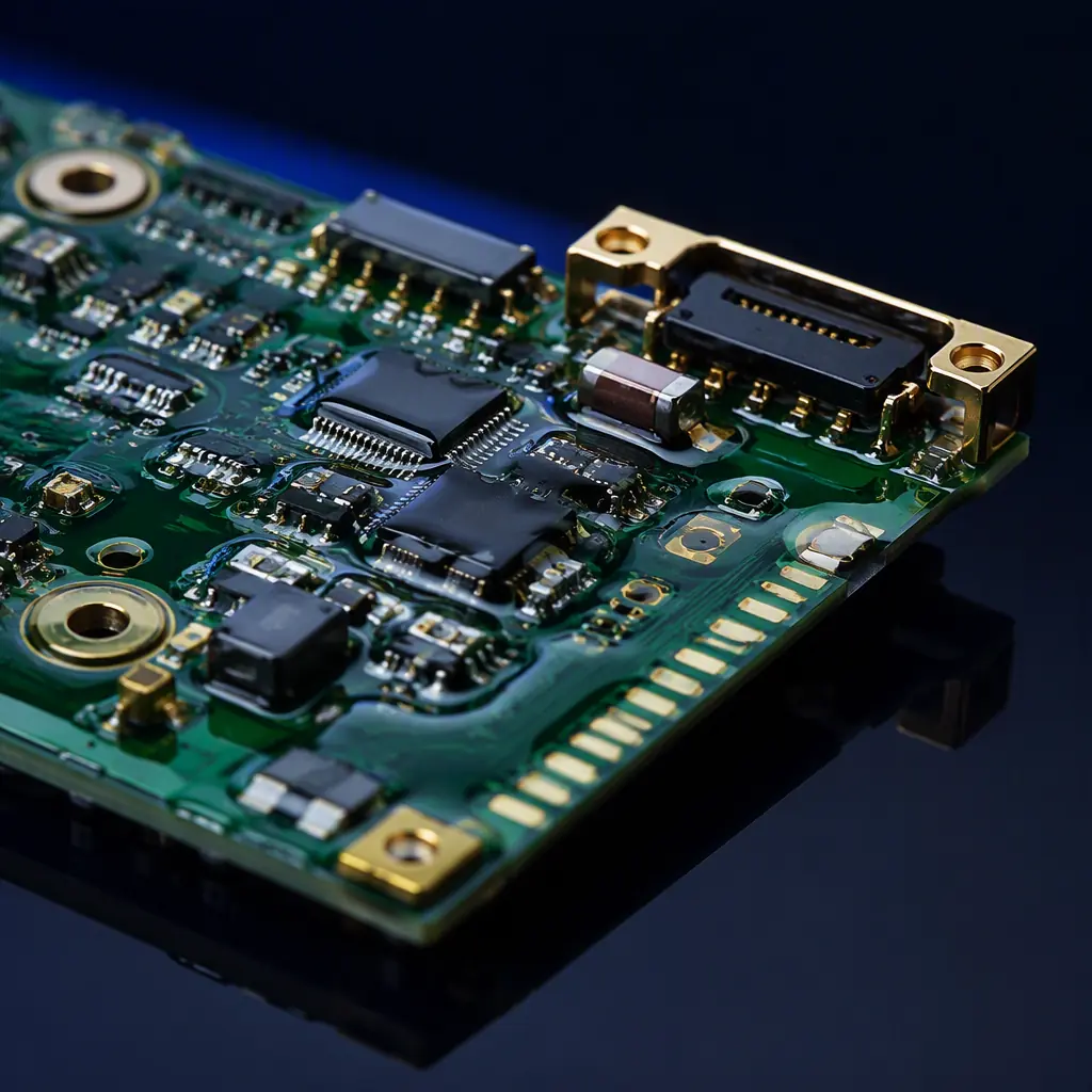
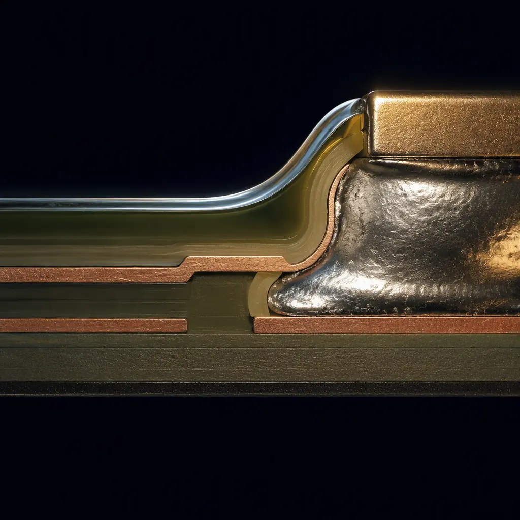
The coating must be continuous and contiguous over the protected area. On a Class 3 board, the entire area under the coating must be covered with no exposed conductor or solder joint; on Class 2, small, non-functional areas outside the required zone may be exempt. The coverage boundary, the keep-out zone around connectors, test points and shielding, must be fully respected. This is the single most common reject at incoming inspection, and the easiest to verify visually with UV light.
Film thickness
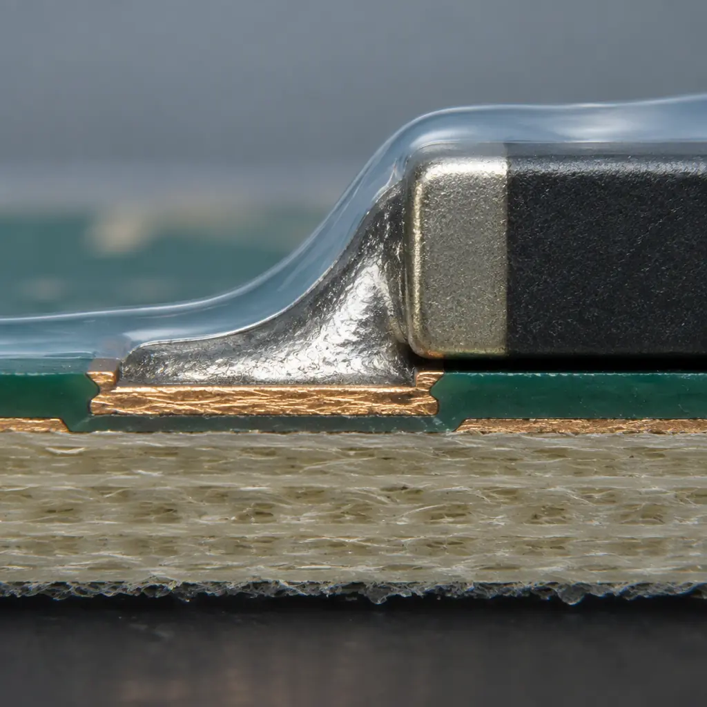
Thickness is measured as dry film thickness (DFT) after curing, and IPC-A-610 references the ranges in IPC-CC-830. As a rule of thumb, acrylic and urethane target 25–75 µm, silicone 50–200 µm, and parylene 5–50 µm. Under-coating is the more dangerous failure than over-coating: too thin a film leaves moisture a path to the copper. The acceptance rule is that the minimum DFT must meet the specified value for the material class, and measurement must be on the actual board, not on a coupon.
Voids, bubbles and pinholes
Voids and bubbles in the film are acceptance criterion items. Small, isolated bubbles may be acceptable on Class 1 and Class 2, but any bubble or void that bridges two conductors, or that punctures the film and exposes copper, is a reject at every class. Pinholes, tiny breaks in the film, are the highest-risk defect because they localize moisture and create a point of electrochemical migration. On Class 3, pinholes are typically a reject outright, or restricted to a small per-unit-area count. Ionic contamination behind an incomplete film is where field failures actually start.
Adhesion
The coating must adhere to the substrate and component surfaces without cracking, flaking or lifting. Lifting or blistering around component corners, leads and connectors is a common defect caused by insufficient surface preparation or a too-thick film over sharp edges. IPC-A-610 requires that coating show no evidence of poor adhesion, and the way to prove it is a cross-hatch tape or pull test on a sample. Adhesion matters most around BGA and fine-pitch packages, where sharp lead profiles stress the film.
No coating on prohibited areas
Connectors, gold fingers, mechanical fit surfaces, optical windows, and the underside of certain components must remain uncoated. On a Class 3 board, coating on a prohibited contact area is generally a reject. This is why our automated selective coating uses programmable dispensing that physically avoids keep-out zones rather than relying on hand masking. Masking labor is where coverage mistakes creep in, and it is often the difference between a pass and a fail.
Key Takeaway: IPC-A-610's coating criteria are coverage, thickness, voids, adhesion, and keep-out discipline. Not "looks shiny." The fastest way to filter a supplier is to ask for their DFT measurement records and UV inspection logs on the last 10 lots, rather than trusting a blanket "compliant" claim.
How Acceptance Stringency Scales by Class
Class is the lever that changes everything. The same coated board that passes Class 2 often fails Class 3. Here is how the coating criteria tighten as the class rises:
| Criterion | Class 1 (Consumer) | Class 2 (Industrial) | Class 3 (High-reliability) |
|---|---|---|---|
| Voids / bubbles | Small, isolated OK | No bridging conductors | Minimal, tightly controlled |
| Pinholes | Generally not controlled | No exposure of copper | Typically a reject |
| Film thickness control | Ranges only | Minimum by material | Minimum + documented records |
| Coating on prohibited areas | Tolerance to minor overspill | Function-affecting reject | Reject; no mask conflict |
| Adhesion verification | Visual only | Abraded / scuff test on samples | Cross-hatch + qualification records |
If your product is automotive, medical, aerospace or military, treat it as Class 3 regardless of what the box says. A coated board that is under-specified to Class 2 when the end environment demands Class 3 is a latent failure, not a savings. Our second-run testing methods comparison shows how coating inspection fits into the wider verification stack.
How to Verify a Coated Board Conforms
Acceptance criteria are only useful if you can actually measure them. Four practical inspection methods cover almost every IPC-A-610 coating criterion:
UV-A illumination, coverage and void detection
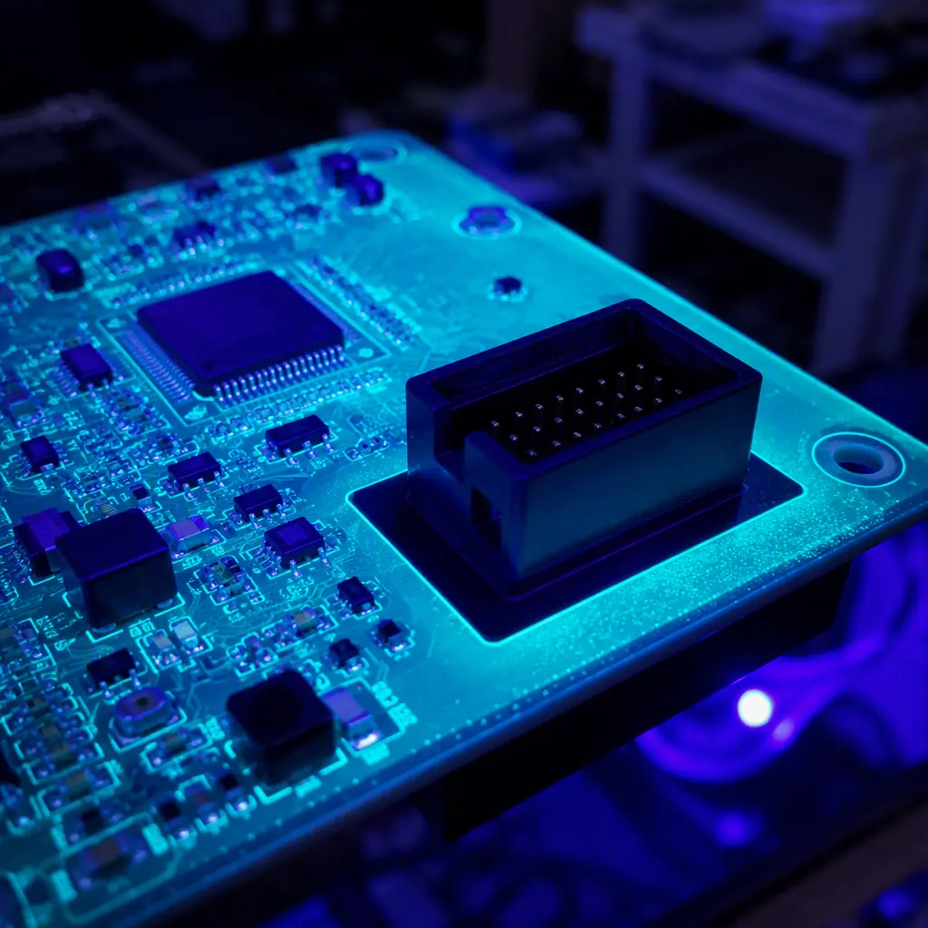
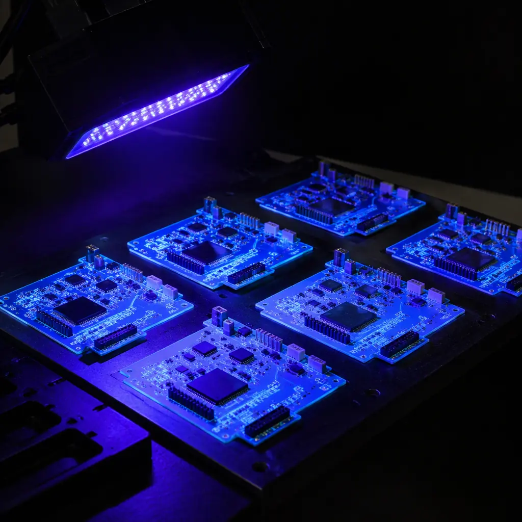
Most conformal coatings contain a UV fluorescent tracer. Under 365 nm UV light, a coated area fluoresces while uncoated or bare areas stay dark. This makes coverage gaps, bubbles, thin areas and keep-out violations instantly visible. It is the fastest and most reliable first-pass screen: it catches roughly 95% of coating defects in under a couple of seconds per board. At Huaxing, every coated board passes automated UV cameras with AI defect classification.
Microscope at defined magnification
Pinholes, blisters, cracks and edge lift require magnification. IPC-A-610 inspection is methodical at low power first and higher magnification when a suspect is found. Pinholes are often invisible to the naked eye; a 10–30× microscope finds them.
Wet film thickness comb / dry film thickness measurement
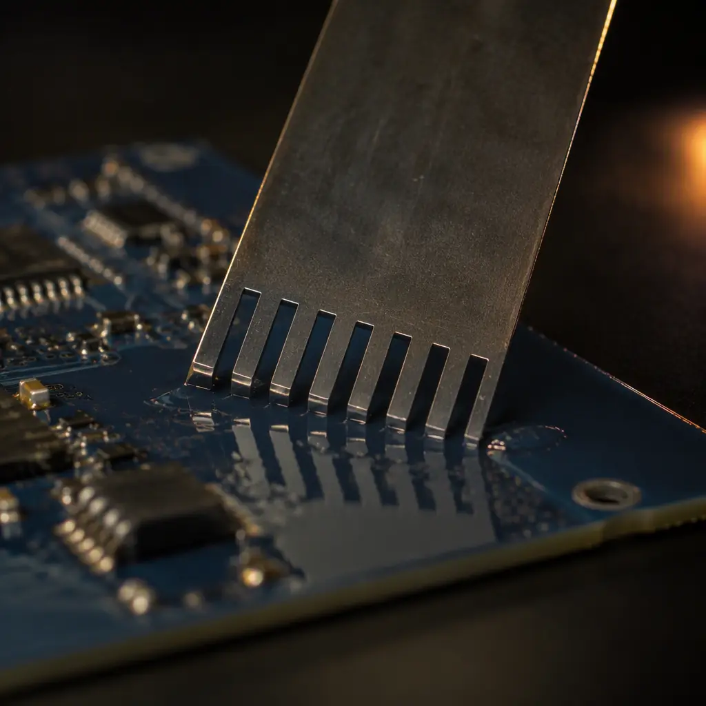
A wet-film comb gauge reads thickness immediately after application; dry film thickness is wet thickness multiplied by the solids content (typically 20–35% for solvent-based acrylics). For production evidence, a non-destructive DFT probe or a sacrificial coupon cross-section is used. This is the number that separates a 15 µm decorative film from a real 50 µm protective one.
Cross-hatch adhesion / tape test
A cross-cut grid is scored into the cured film, pressure-sensitive tape is applied and peeled, and the amount of removed film is rated per IPC-CC-830 / ISO 2409. This directly verifies the adhesion criterion and is the only quantitative way to catch poor surface prep before it becomes a field delamination.
Putting the Acceptance Criteria in Your Purchase Order
Vague coating specs are where quality escapes happen. A single line that says "conformal coated, IPC-A-610 compliant" gives you nothing to inspect against. Instead, spell out five things so there is no negotiation at incoming inspection:
The material class and target DFT
e.g. "UR (urethane), 50–75 µm dry film thickness, per IPC-CC-830." This eliminates the $0.15 versus $1.80-per-board ambiguity entirely.
The acceptance class
State Class 2 or Class 3 explicitly, and point to IPC-A-610 as the reference. Then define how voids, pinholes and adhesion are judged.
The keep-out zones
List the connectors, test points, gold fingers and optical areas that must remain uncoated, and state that they will be inspected. Our gold finger design guide shows why edge contacts are the most common keep-out casualty.
Inspection records and first article
Require DFT readings and UV inspection logs with the shipment, and a documented first-article inspection before the run. This ties the acceptance criteria to a verifiable artifact rather than an assertion.
Sampling and disposition
Agree the AQL sampling plan for coated boards and what happens on a reject (rework, re-inspection, or full reset). Removing coating for rework is real cost, so the plan should make the supplier correct the root cause in process.
Procurement Tip: A coated board is only worth what you specify and verify. Buyers who put "per IPC-A-610, Class 3, urethane 50–75 µm DFT, UV-inspected, DFT records supplied" in the order get consistent, inspectable boards. Buyers who write "coated to protect from moisture" get whatever is cheapest.
The 10-Second Buyer's Checklist
Key Takeaway: IPC-A-610 conformal coating acceptance turns on coverage, thickness, voids, adhesion and keep-out discipline, and each one gets stricter from Class 1 to Class 3. Draw the line in your purchase order with a material class, a target DFT, an explicit acceptance level, and a documented first-article inspection. If you cannot state the DFT range and the class in the order, you are buying a gamble.
Which Clause Governs Which Defect
The most common argument at a coating inspection bench is not about whether a board is good — it is about which rule applies. A rejected lot will cite a clause number, and if that clause does not actually cover the condition in question the rejection is appealable. The table below maps the conditions that generate almost all coating disputes to the clause family that governs them and the verdict that changes between classes.
| Condition | Governing requirement | Class 1 | Class 2 | Class 3 |
|---|---|---|---|---|
| Void or bubble in the film | Coating voids / bubbles | Accept if no exposed conductor | Accept if no exposed conductor | Not permitted over conductor or joint |
| Dewetting or orange peel | Coating adhesion / surface | Accept | Accept if adhesion intact | Evaluate — may indicate contamination |
| Coating on connector contacts | Keep-out / connector areas | Not permitted | Not permitted | Not permitted |
| Coating in a keep-out zone | Coating coverage limits | Not permitted | Not permitted | Not permitted |
| Coating on a test point | Coating coverage limits | Evaluate | Evaluate | Evaluate — must remain probeable |
| Uncoated conductor edge | Minimum coverage | Accept if protected | Not permitted | Not permitted |
| Coating bridging two pads | Coating between conductors | Accept if no electrical effect | Evaluate | Not permitted |
| Meniscus lifting at a coating edge | Coating adhesion | Accept | Accept if stable | Evaluate |
| Coating on a mating surface | Keep-out / mating surfaces | Not permitted | Not permitted | Not permitted |
Two patterns emerge from that table and both are worth understanding before a dispute starts. The keep-out rules — connectors, mating surfaces, designated zones — do not relax between classes. A coating on a connector contact is a defect at Class 1 exactly as it is at Class 3, because the failure mode is mechanical and electrical rather than a matter of reliability margin. Conversely, film-quality conditions such as voids, bubbles and dewetting relax substantially from Class 3 down to Class 1, because the question becomes whether the conductor is still protected rather than whether the film is flawless.
Useful in an argument: if a supplier rejects a lot for "coating defects" without naming a clause, ask which condition and which class. If the condition is a void, dewet or bubble and the assembly is Class 1 or 2 with no conductor exposed, the rejection may not be supported. If the condition is coating on a connector or in a keep-out, the rejection holds at every class.

Class 1 vs Class 2 vs Class 3 — Where the Verdict Actually Changes
Coating vendors and assembly marketing material like to imply that Class 3 is dramatically stricter across the board. In practice the stringency is concentrated in a small number of places, and knowing exactly where saves both over-coating cost and unnecessary rejection.
Where the class genuinely changes the outcome: film defects over conductive features. A void over a solder joint is tolerable at Class 1 and 2 if no conductor is exposed and the joint remains protected; at Class 3 the film is expected to be continuous over the joint. The same applies to pinholing and to thin spots over traces, where Class 3 expects verification against a minimum thickness rather than a visual judgement.
Where the class does not change the outcome: anything that destroys function regardless of reliability margin. Coating inside a connector, on a mating surface, on a press-fit pin or across a card-edge contact is a defect at all three classes. So is coating that has bridged two conductors where bridging changes the circuit. Arguing that a Class 1 product tolerates coating on its connector is not a defensible position.
Where the class changes the evidence required rather than the visual verdict: thickness verification and inspection records. A Class 3 assembly is expected to have documented thickness measurement at defined points and a photographic record of the coated zones. A Class 1 assembly may be accepted on visual inspection alone. This is the difference that most often surprises buyers — they assume the higher class means a visually better board, when it usually means a better documented one.
The Evidence Package a Buyer Should Require
Acceptance criteria only work if there is evidence behind the claim of conformance. A supplier saying "coated to IPC-A-610 Class 2" is a statement of intent; the package below is what converts it into something you can audit. Ask for it on the first article and on any lot where the process changed.
Thickness measurement method, named
Eddy current, ultrasonic and microsection do not measure the same thing. Eddy current reads the film over a conductive substrate and is non-destructive but sensitive to the underlying copper; ultrasonic works over non-conductive substrates and is less common; microsection is destructive, definitive, and the only method that shows the film over a specific joint. The specification should name the method, not just the target thickness. Our thickness control guide covers the tolerances each method can actually hold.
Measurement points per board, stated as a count
A single measurement on a 200 × 150 mm assembly proves nothing about the film 80 mm away. Ask how many points are measured per board, where they are located relative to the coating spray pattern, and whether the locations are fixed or chosen by the operator. Five fixed points including the thinnest expected region is a reasonable minimum for a board of that size.
UV inspection record
Most conformal coatings carry a UV tracer precisely so coverage can be verified under a black light. A UV inspection photograph per lot, kept against the lot number, is inexpensive evidence that the coating reached the areas the drawing requires and stayed out of the keep-outs. If the supplier has no UV record, ask why the tracer is there.
Cure verification
An under-cured film passes visual inspection and fails in the field, because the solvent retained in the film attacks the very surfaces it was meant to protect. Cure verification can be a solvent rub, a hardness test, a DSC run or a defined oven profile record with a thermocouple trace. Which one matters less than that one exists. The material side of this is covered in our IPC-CC-830 qualification guide.
Material lot and shelf-life traceability
The coating lot number should appear on the inspection record, and it should be within shelf life at the time of application. Coatings that have sat past their date behave differently at cure, and the resulting film may pass visual inspection while failing adhesion. This is a documentation check, not a test, and it costs nothing to demand.
Does IPC-A-610 Specify a Coating Thickness?
The short answer: IPC-A-610 does not set a numeric coating thickness. It sets visual acceptance criteria for coverage, voids and keep-outs, and it requires that thickness be verified where the drawing specifies one. The thickness itself comes from the material datasheet and from the qualification of that material to IPC-CC-830 — which is why a purchase order that names only "IPC-A-610 Class 2" without a thickness range leaves the most important variable unspecified.
This is the single most consequential misunderstanding in coating procurement. A buyer who specifies only the class has specified how the film should look, not how thick it should be. Typical design targets sit between 25 and 75 microns for acrylic and urethane coatings and considerably thinner for parylene, but those numbers come from the material and the environment, not from the inspection standard. Our coating types comparison sets out the ranges by chemistry, and the outgassing guide explains why thickness becomes a hard constraint in vacuum applications.

Summary, Make the Criteria Controllable
Conformal coating is a cheap, high-value reliability measure only if you can judge it. By writing the IPC-A-610 criteria, class, thickness, void and pinhole limits, keep-out zones and inspection evidence, into your specification, you turn a hand-waving "compliant" claim into a measurable, inspectable requirement.
At Huaxing PCBA we apply conformal coating across our 8 SMT lines with automated selective dispensing and UV inspection on every board, processing over 8 million placements per day. We provide DFT and UV inspection records with coated lots and a documented first-article inspection against an agreed IPC-A-610 Class. We are ISO 9001, IATF 16949 and UL certified, and we serve procurement and engineering teams from 30+ countries. Upload your files for a quote or talk to our engineering team about your coating specification and acceptance plan.