
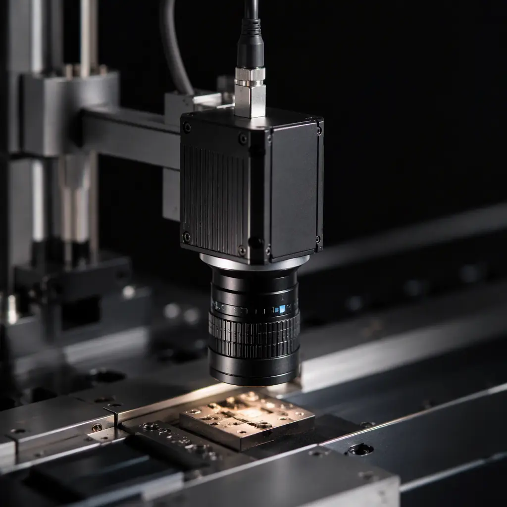
When an integrator specifies a machine vision camera for an inspection station, they are not shopping for image quality alone. They are specifying a device that must trigger to a shaft encoder, deliver a frame to a vision controller in a fixed budget, and run unattended for years in a factory. The board behind the sensor has to satisfy all of it at once, and the interface choice, the sensor timing and the thermal/EMI design decide whether the system actually meets its throughput number.
The difference from a consumer camera is engineering discipline, not just components. A consumer module may tolerate a dropped frame and a warm image. A vision camera cannot: a missed trigger means a missed inspection, and a thermal drift means a tolerance decision made on an unstable reading. At Huaxing PCBA we build vision and imaging boards across 8 SMT lines in a 15,000 m² facility, with the 3/3 mil trace capability and 32-layer stackups that high-density sensor front-ends demand.
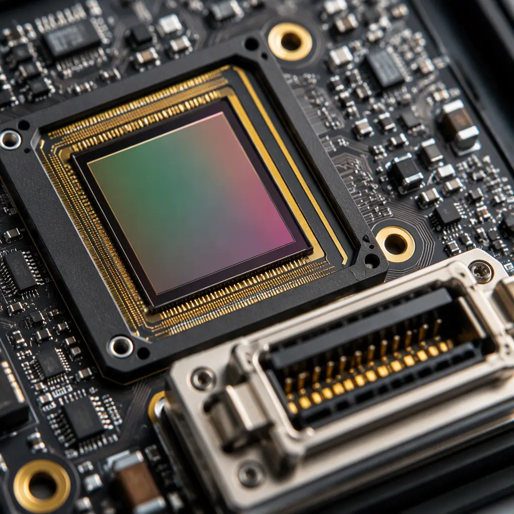
Which Vision Interface: GigE Vision, USB3 Vision or CoaXPress
The single biggest design decision is the output interface, because it fixes the connector, the cable, the PCB routing budget, the frame-rate ceiling and the power budget all at once. Picking the wrong one is expensive to change later, so it is worth getting right at the schematic stage rather than at the field-upgrade stage.
| Interface | Typical bandwidth | Max cable length | PCB design impact | Best fit |
|---|---|---|---|---|
| GigE Vision (1 GbE) | ~120 MB/s | Up to 100 m | RJ45 + magnetics, 100Ω differential pairs | Multi-camera plants, long runs |
| 2.5G/5G/10G Ethernet | 300–1200 MB/s | 10–100 m | High-speed differentials, low-loss laminate, heatsink | High frame-rate inspection |
| USB3 Vision | ~350 MB/s (USB3) | Up to 5 m (active cable more) | SuperSpeed pairs, shielded cable | Lab switching, portable rigs |
| CoaXPress (MTP/BNC) | 6.25 Gbps per lane, up to 4 lanes | Up to 100 m+ | Single-ended 75Ω coax, very high-speed | Line-scan, extreme resolution |
For a normal multi-camera cell, GigE Vision is the pragmatic default because standard Ethernet hardware keeps the Bill of Materials down and the cabling simple. The caveat is that the differential pairs for the Ethernet PHY need tight impedance control and clean reference planes, the kind of discipline our Ethernet PHY design guide explains in detail. For the highest-throughput line-scan and area-scan applications that outrun Ethernet, CoaXPress becomes the only realistic answer, and that pushes the board into genuinely high-speed territory.
Global Shutter vs Rolling Shutter: The Timing Decision
For a moving object, a part on a conveyor, a web of material, a printed circuit moving past an inspection head, the shutter type determines whether the image is sharp or distorted. A rolling-shutter sensor exposes rows sequentially, so fast motion smears. A global-shutter sensor exposes the whole array at once, freezing motion. In machine vision, motion is almost always present, which is why global-shutter sensors dominate industrial cameras the way 1/1.8" to 1.1" global sensors do.
Sensor clocking and the analog front-end
The sensor is clocked by a precise crystal and the analog output is conditioned before the ADC. This is a genuinely mixed-signal area: the analogue supply needs quiet regulation and the sampling clock needs low jitter or the image shows column noise and banding. Our mixed-signal PCB design guide covers the grounding and partitioning that this demands.
Trigger and exposure synchronisation
The camera must expose at exactly the moment the part arrives. That means a low-latency, well-shielded trigger input, and on multi-camera systems a synchronisation signal that keeps every head on the same cycle. Poor trigger routing produces a system that passes static shots and fails on the line, which is the worst failure mode of all.
Sensor supply hygiene
Image sensors are sensitive to ripple and droop on the analogue rails. A decoupling strategy that is merely adequate for a digital board will produce low-level noise in the image that an inspection algorithm then misreads. This is where a real power-integrity review pays for itself, see our power integrity and PDN design guide.
Key Takeaway: For any camera that sees motion, specify a global-shutter sensor and treat the sensor supply as analogue, not digital. A clean clock, a quiet analogue rail and a fast, shielded trigger input are what separate a vision camera from a phone module.
Why Thermal Design Bounds Real-World Frame Rate
A sensor that runs hot develops dark current, which shows up as brightness and noise that drift with temperature. In a vision system the consequence is an inspection that slowly becomes less repeatable as the camera warms up during a shift. A sensor that runs cooler reaches its stabilised operating point quickly and stays there. So the thermal path is a repeatability feature, not a nicety.
The thermal budget is set by the sensor, the FPGA or SoC that processes the image, and the interface chip. A modern global shutter sensor plus a small FPGA can dissipate 2–5 W inside an enclosure that is often sealed against dust. The board has to move that heat out through planes, thermal vias and, on metal-housed cameras, the board-to-housing interface.
In a sealed housing with no airflow, copper pours and thermal vias become the only heat path. Our PCB thermal management guide and copper weight selection article are the two places to start when you are trying to keep a sealed vision camera at a stable temperature.
EMI and the Factory EMC Environment
Machine vision cameras run next to variable-frequency drives, welding equipment, motors and switching power supplies, a genuinely harsh electromagnetic environment. At the same time the camera is itself a radiator, because fast digital signals and high-frequency interfaces couple to the enclosure and to the cable. A camera that cannot meet its emissions budget and its immunity budget is a source of flaky inspections and is a liability in a CE or UL-marked system.
Return paths and reference planes
Every high-speed return current needs a solid reference plane beneath it. Gaps and slots create loops that couple to the outside. Layout discipline here is what makes an emissions profile pass on the first attempt, our EMC/EMI compliance guide details the approach.
Shielding and the board-to-housing ground
The aluminium housing of an industrial camera is the shield, but it only works if the board references it with a low-impedance ground at the mounting points and through the I/O connector. Clamp the board's ground to the housing using the correct mounting and earthing scheme.
Conformal coating and environmental protection
Many vision cameras operate in dirty, dusty or humid environments. A conformal coating protects the board from condensation and particulate ingress without adding thermal resistance if it is applied correctly. Our conformal coating guide covers the material and thickness trade-offs.
The Factory-Hardened Design Checklist
A vision camera that is specified for industrial use has a set of requirements that a consumer camera simply does not carry. The checklist below is the one to run against any candidate board before you commit to a supplier, because these are the items that show up as field failures if they are skipped.
| Requirement | Typical industrial spec | Why it matters |
|---|---|---|
| Operating temperature | 0–50°C, sometimes −10–60°C | Stabilised image across a shift |
| Connector robustness | Locking connector (M12 / push-pull) | Vibration must not unplug it |
| Vibration tolerance | IEC 60068-2-6 | Mechanical reliability on moving equipment |
| Power input | Wide input, reverse-protected | Often powered from the machine's 12 / 24 V rail |
| Trigger latency | Microsecond-level, deterministic | Reliable inspection triggering |
| EMC immunity | Per EN 61000-4-x | Survives a factory EMI environment |
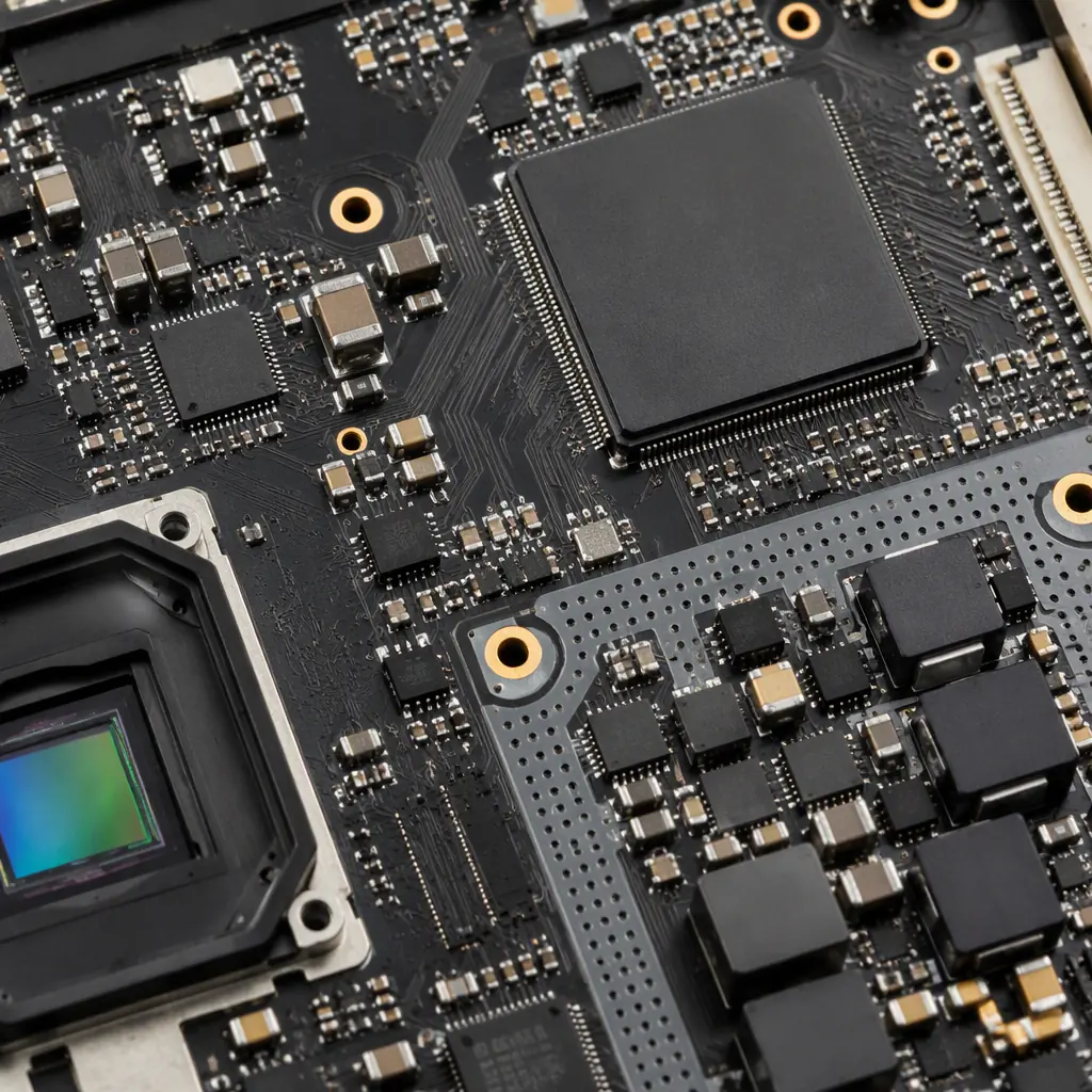
Two further articles round out the picture. For the signal-integrity side of the high-speed interface, PCB signal integrity covers the routing rules that keep a CoaXPress or 10G link clean. And for the testability that a vision board depends on in production, our PCB testing methods guide explains the AOI, X-ray and flying-probe checks that catch defects on a dense sensor board.
Takeaways for Procurement and Engineering
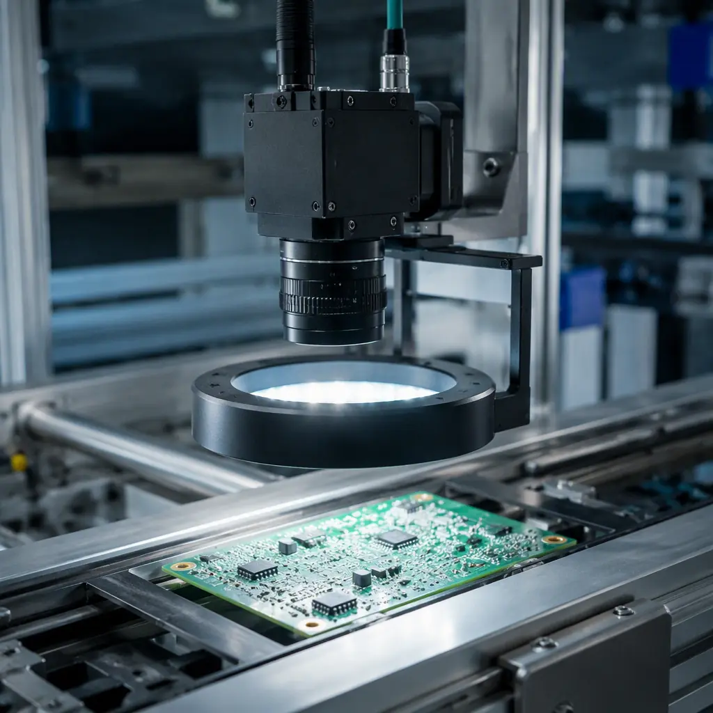
When you specify an industrial machine vision camera, the board is the product. The interface defines the routing and connector budget, the shutter type defines the sensor and its timing, the sensor supply defines the achievable image quality, and the thermal and EMI work defines whether the camera is repeatable in the field. Get those four right and the camera earns its decade of service; get one wrong and no amount of "high resolution" marketing fixes it.
Procurement Tip: Ask your PCBA partner to review the sensor supply, the interface routing and the thermal path as a design deliverable before the first run. A supplier that flags the analogue-rails problem at the schematic stage has just saved you a camera that drifts out of spec after an hour of operation.
At Huaxing PCBA we build high-density imaging and vision boards with 8 SMT lines, 4 DIP lines, 32-layer fabrication and 3/3 mil minimum trace control, in a 15,000 m² facility with 500+ staff serving customers in 30+ countries. We are ISO 9001, IATF 16949 and UL (E354321) certified, with a 99.2% on-time delivery and 98.7% first-pass yield. Upload your design for a quote or talk to our engineering team about a machine vision board. For the surrounding system context, start with our industrial control PCB and network switch guides.
