
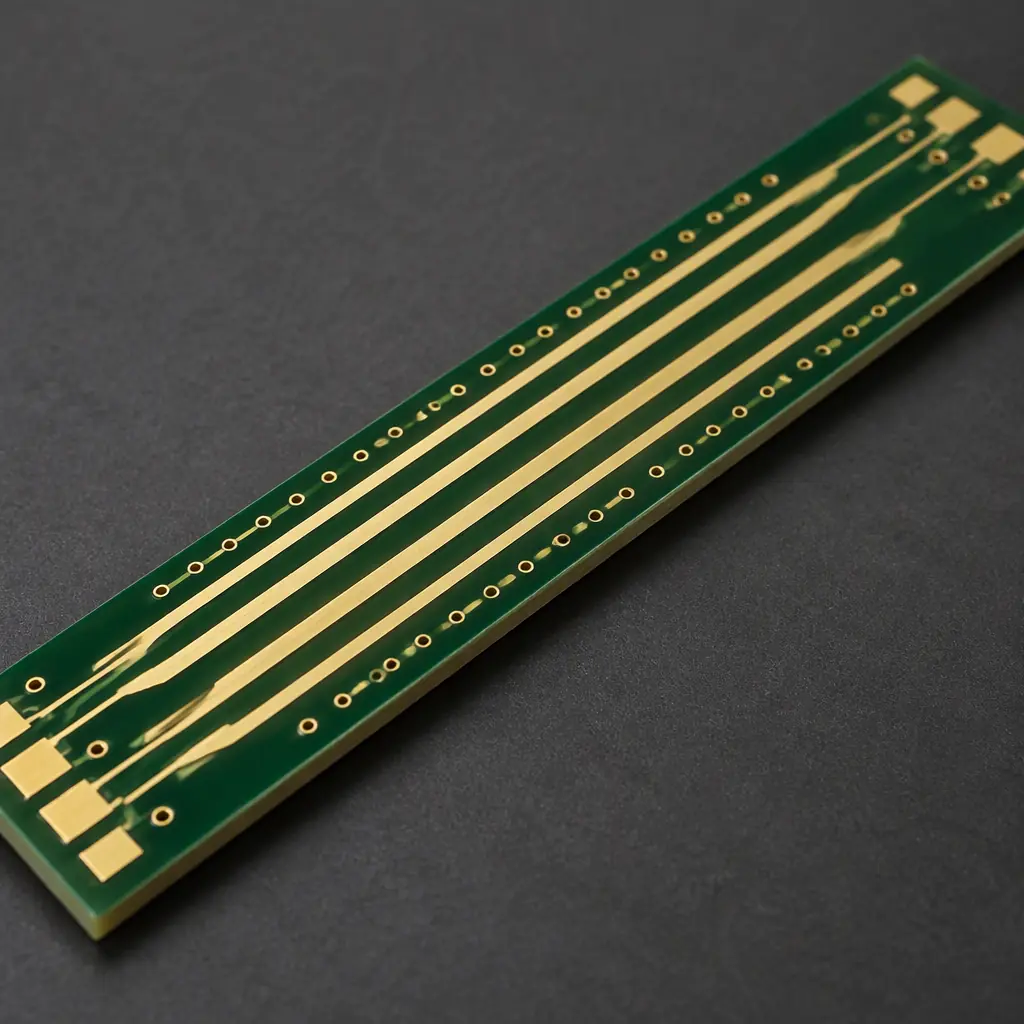
Controlled impedance is a stackup promise. The designer selects a target — often 50 Ω single-ended or 90–100 Ω differential — and the fabricator builds a dielectric height, trace width and copper thickness combination intended to hit it. Nothing in the finished board lets you measure that directly without cutting it open or letting a high-frequency signal misbehave at the end of a program. The impedance test coupon exists to close that gap: it is a set of traces built from the same stackup, on the same panel, measured with time-domain reflectometry to confirm the process landed on target.
Coupons are only as good as their design and their sampling. A coupon that is not representative of the board, or that is measured once per program and never again, gives false comfort. Understanding what makes a coupon valid is the same discipline as understanding what makes any test coupon meaningful: the test structure must isolate the property you are trying to verify.
Why a Coupon Is Not the Board
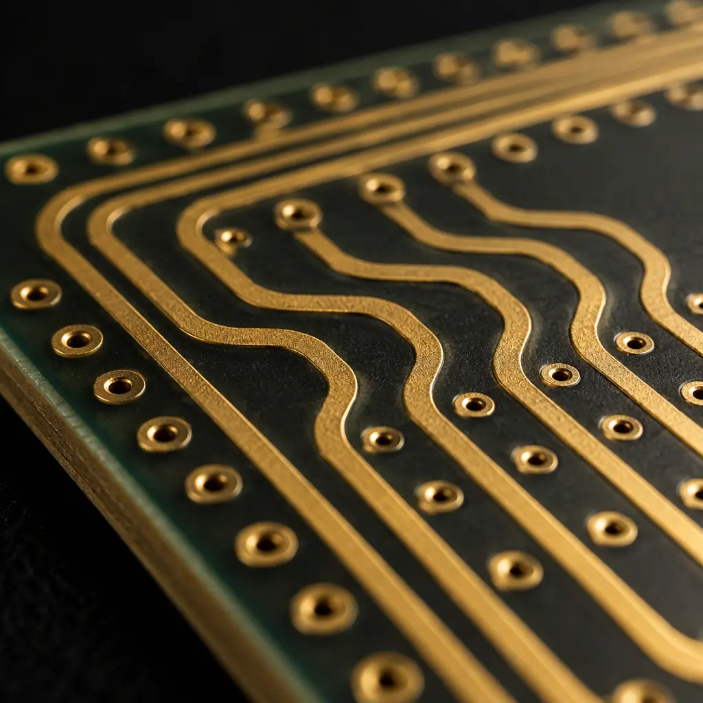
The coupon is fabricated on the same panel as the product, from the same cores and prepreg, through the same lamination and etch steps. That shared history is what makes it evidence. What makes it different is geometry: the coupon is a small, isolated structure with its own launch points, its own reference planes, and often a ground fence around each trace. Those differences are deliberate — they isolate the impedance from coupling and from connector effects — but they also mean the coupon will never read the same as a trace buried in the actual board.
Three design features make a coupon representative rather than decorative:
- Reference plane continuity. The coupon trace must sit over solid copper with the same dielectric height and the same reference layer as the board. A coupon built over a split plane reads differently and tells you nothing about the product.
- Ground fencing and launch geometry. The test trace needs ground vias flanking it at a defined pitch and a launch that lets the probe or connector couple cleanly. Without a controlled launch, the measurement includes the fixture, not the trace.
- Same trace width and finish as the product. The coupon must use the product's routed trace width and the same surface finish. A coupon on a different finish, or with a width rounded to a convenient value, is a different transmission line.
Coupon Design Requirements
A coupon that will be measured with TDR needs a few specifics that are easy to leave off, and that determine whether the resulting report is usable. The table below lists the requirements a fabricator needs stated on the drawing so the coupon can be built and probed correctly.
| Requirement | Typical Value | Why It Matters |
|---|---|---|
| Trace length | ≥ 100 mm (4 in) | separates the launch from the settled impedance plateau |
| Ground via pitch | ≤ λ/10 at the highest frequency | prevents fence resonance in the measurement window |
| Reference plane | solid, same layer as product | dielectric height must match the board |
| Coupon severing | break-away tab, no v-score through traces | clean edge for probing |
| Trace types | single-ended + differential on the same coupon | one report covers both requirements |
One requirement that is frequently omitted is the coupon's independence from the panel rail. If the coupon shares a v-score line with the product, separating the boards can stress the coupon traces and shift the measured value. Specify a break-away tab so the coupon is parted without loading the transmission line. The same breakaway thinking that governs panelization and cost applies to coupon placement — putting the coupon where it can be cleanly separated costs nothing and protects the measurement.
What the TDR Report Actually Shows
A time-domain reflectometry report is a plot of impedance against electrical length, derived from the reflections a fast edge produces as it travels down the trace. The instrument launches a step, records the reflected voltage, and converts that to an impedance profile. Reading it well means knowing which part of the trace you are trusting.
The report normally shows a launch spike, a settled plateau, and a termination artifact. The value you care about is the plateau — the flat region in the middle of the electrical length — not the spike at the connector or the tail near the far end. A single number quoted on a report is almost always the average of that plateau, and the acceptance decision should be based on it rather than on the peak-to-peak excursion of the whole trace.

Acceptance Criteria and Tolerances
Most controlled-impedance programs accept ±10% of the target, with tighter ±5% reserved for high-speed serial links where the margin is thin. The tolerance applies to the plateau value, and it applies per trace type. A report that passes single-ended but drifts on differential is a real finding, not noise, because the two trace geometries respond to different process variables.
| Trace Type | Typical Target | Routine Tol. | Tight Tol. |
|---|---|---|---|
| Single-ended microstrip | 50 Ω | ±10% | ±5% |
| Single-ended stripline | 50 Ω | ±10% | ±5% |
| Differential pair | 90 / 100 Ω | ±10% | ±7% |
| Coplanar waveguide | 50 Ω | ±10% | ±7% |
The values assume the coupon is measured with the finish on, at a controlled temperature, and with a properly de-embedded launch. Measuring a coupon on a different finish or without correcting for the probe introduces an error that can exceed the tolerance itself. This is why the coupon's surface finish must match the product's — the same reasoning that governs any controlled-impedance decision on the shop floor.
Sampling Plan and Cost
How often to test is a cost-versus-confidence decision. Three sampling strategies cover most programs:
- Per program (first article). Measure once, at first article, to validate the stackup and the etch process. Lowest cost, but it does not catch drift later in the run.
- Per lot. Measure one coupon per production lot. A reasonable middle ground for programs where the material and process are stable and the consequence of a miss is moderate.
- Per panel. Measure every panel. Highest cost and only justified for high-reliability or high-speed programs where a single out-of-spec panel is unacceptable.
The cost of coupon testing is dominated by the test time and the report, not the coupon itself — the coupon rides on the panel at effectively no material cost. That makes per-lot testing the usual recommendation for a program that has already passed first article, and per-panel testing a deliberate choice for the programs that need it.
When a Coupon Fails: The Corrective Loop
A failing coupon is a process finding, not automatically a scrap event. The right response depends on what the TDR report shows, and the first question is always whether the coupon or the board is the source of the deviation.
- Re-measure on a second coupon from the same panel. A single outlier is often a launch or probe artifact. If the second coupon reads in tolerance, the first measurement is suspect.
- Check the direction of the error. Low impedance generally points to a thinner dielectric, a wider trace, or a higher copper thickness than designed. High impedance points the other way. The direction tells the fabricator which process variable moved.
- Adjust the stackup or the trace width and re-etch. If the deviation is within a few percent, a trace-width tweak recovers the target. Larger deviations point to a material or lamination issue that has to be corrected at the stackup level.
- Re-run the coupon, then confirm on the board. Close the loop by measuring the new coupon, and, where the program allows, a microsectioned sample of the product to confirm the actual dielectric height matches the corrected coupon.
What you should not do is average the failing readings against a passing one, or accept a report whose single quoted number hides a plateau that was out of tolerance. The report is evidence; read the trace, not just the headline figure. Microsection data complements the coupon and is the natural cross-check, the same way a microsection analysis confirms plating and via geometry that electrical test cannot see.
Specifying Impedance Control on Your Fab Drawing
The callout that gets the result you want names the target impedance, the tolerance, the trace type, the reference layer, and the sampling frequency. A useful form is: "controlled impedance, 50 Ω ±10%, microstrip on L1 over L2, coupon per panel, TDR report required with each shipment." Add the differential requirement as a separate line with its own target and tolerance, and state the coupon trace length and ground fence pitch so the coupon is built to be measured.
Stackup, coupon and acceptance all belong to one conversation. If the stackup design is still fluid, settle it before the coupon is drawn, because a coupon built to a provisional stackup will not match the board that ships.
At Huaxing PCBA controlled-impedance programs are quoted with a stackup review, and the impedance coupon is designed alongside the board so the reference plane, trace geometry and finish match the product. We measure with TDR and deliver the report as part of the shipment documentation, and we hold ±10% as routine with ±5% available on high-speed programs, across builds up to 32 layers. Send your Gerber, stackup and impedance requirements for a quote or talk to an engineer about your coupon and sampling plan.
