

Every product that carries a clock above a few tens of megahertz — a radio, a switching regulator, a fast processor bus — radiates something, and the board is where most of it originates and where the cheapest place to stop it exists. Board-level shielding sits on the assembled PCB, close to the source, and does the job that a plastic enclosure full of copper paint can only do crudely. This guide is written for the buyer and the hardware engineer who must specify that shield at the quote stage, because the choice they make on the drawing is what the assembly house has to build and what the EMC lab will later test under EMC and EMI compliance.
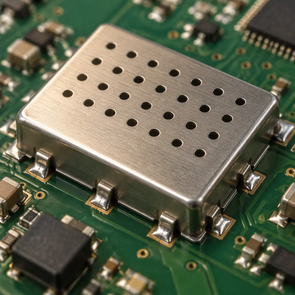
What a Board-Level Shield Actually Does
A metal shield works by reflecting and absorbing electromagnetic energy that would otherwise leave the board, and by returning energy that would otherwise couple into a sensitive circuit. Its performance is measured as shielding effectiveness (SE) in decibels — the ratio of field strength without the shield to field strength with it. For most commercial and industrial electronics, the requirements cluster around two useful reference points: 20 dB removes 90% of the incident field and is enough to stop a marginal emission failure, while 40 dB removes 99% and is what a board full of switching noise or a sensitive receiver front-end typically needs.
The metal type matters less than most people assume at these levels. A thin 0.15–0.20 mm stainless steel or nickel-silver can reaches 40 dB easily across the relevant band. What kills performance is not the material — it is leakage through the seams, the openings, and the ground connection. A perfect can with a poor seam behaves like a good antenna.
Stamped Can vs Fence-and-Lid vs Board-Level Gasket
There are three practical ways to shield a board region, and the right one depends on whether the circuit under the shield ever needs to be reworked or tested after assembly.
| Type | How It Is Attached | Removable? | Best For |
|---|---|---|---|
| Stamped can (one-piece) | Soldered on all peripheral tabs | No — desolder to rework | High volume, mature design, no field rework |
| Fence-and-lid (two-piece) | Fence soldered once; lid clips on | Yes — lid lifts off | Test and rework access, medium volume |
| Gasket / clip-on shield | Friction or adhesive, no solder | Yes, repeatedly | Serviceable products, prototyping |
The decision almost always turns on serviceability. If a board under a soldered can ever needs component rework, every rework event becomes a desoldering operation that risks the board, and the shield has to be replaced because stamped tabs rarely survive a second solder cycle. The two-piece fence-and-lid exists precisely to solve this: the fence is soldered once during assembly and never moves, while the lid is a clip-on part that lifts off for test or rework and snaps back on. The trade is a slightly worse seam (a clip is not a solder joint) and a marginally higher part count. For anything with a realistic rework expectation, that trade is worth it.
Shielding Effectiveness Fallback: Fixing a Failing Board Without a Can
Not every emission problem needs a full shield, and reaching for the most expensive option first is a common and costly reflex. Before tooling a can, run the cheaper fixes in order:
- Slow the edge. A series resistor or ferrite bead on the offending clock or switching node reduces the harmonic energy that radiates. This is the cheapest fix and often buys 6–10 dB.
- Fix the return path. A high-speed signal that returns on a distant ground plane forms a loop antenna. Moving the return directly under the trace, or adding stitching vias along the edge, often removes the emission entirely. This is the same discipline that governs power integrity and high-speed stackup design.
- Local filtering. A feedthrough capacitor or a pi-filter on the connector pin that radiates can suppress the emission at its exit point.
- Partial shielding. A small fence over only the switching regulator, rather than a can over the whole board, captures most of the benefit at a fraction of the cost.
Only when those have been exhausted does a full board-region shield become the right answer. Going through this ladder in order is the difference between a shielding cost of a few cents per unit and a two-piece shield that adds meaningful tooling and per-unit expense.

The Seam, the Gasket and the Ground
Once a shield is chosen, its real performance is set at the seam — the line where the shield meets the board, or where the lid meets the fence. Currents induced in the shield must flow to ground, and any gap longer than a fraction of the wavelength of the highest frequency of concern lets energy leak. The practical rules:
- Ground-stitch vias densely along the fence footprint. A via every few millimetres ties the fence to the ground plane and shortens the return path. A fence soldered to a pad with no vias under it is a floating radiator.
- Keep seam gaps short. The longest unbroken seam segment should stay well below a quarter-wavelength of the highest frequency you must attenuate. At 1 GHz, a quarter-wavelength is about 75 mm in air — much shorter inside a dielectric, so treat any gap over a few millimetres as a leak.
- Use a conductive gasket where the seam cannot be soldered. Conductive elastomer or fabric-over-foam gaskets bridge the gap between a removable lid and the fence. Their compression force must match the clip or screw retention, or the gasket does nothing.
The ground connection is where an otherwise good shield most often fails. Specifying the fence footprint with a continuous row of ground vias — the same discipline used in EMI/EMC board design — costs nothing at layout time and decides whether the shield performs at its rating or at half of it.
Venting, Thermal and the Cost Drivers
A shield traps heat as well as radiation, and a can over a hot switching regulator will raise the junction temperature of the parts inside. The standard solution is a perforated vent pattern stamped into the can lid. Vents reduce shielding effectiveness slightly, so they should be sized as closed as the thermal requirement allows — small holes on a tight pitch, not large cutouts. If the component under the shield dissipates significant power, a thermal path through the shield (a metal boss or a gap pad to the lid) is often needed, and that path has to be designed together with the board-level thermal solution.
Cost is driven by four things: tooling (a stamped can needs a hard tool, typically a few thousand dollars; a fence-and-lid needs two), material (stainless steel is cheaper than nickel-silver or pre-tinned copper), finish (tin-plated is standard), and assembly labour (soldering fence tabs adds a process step). For a first article, the fence-and-lid is usually the cheaper starting point because the lid can be a simple stamped part and the design can be revised without retooling a fully custom can. When volume grows past a few tens of thousands per year, a one-piece stamped can usually wins on per-unit cost — but only once the design is frozen.
At Huaxing PCBA, shielding hardware is quoted as part of the assembly, with the fence footprint, ground-via pattern and vent requirement reviewed at DFM so the shield and the board are designed together rather than bolted on at the end. We build fence-and-lid and stamped-can shields to IPC-A-610 Class 2 and 3 across the 8 SMT lines in Shenzhen. Send your Gerber and BOM for a quote with shield DFM review or talk to an engineer about your EMC-critical assembly.
