
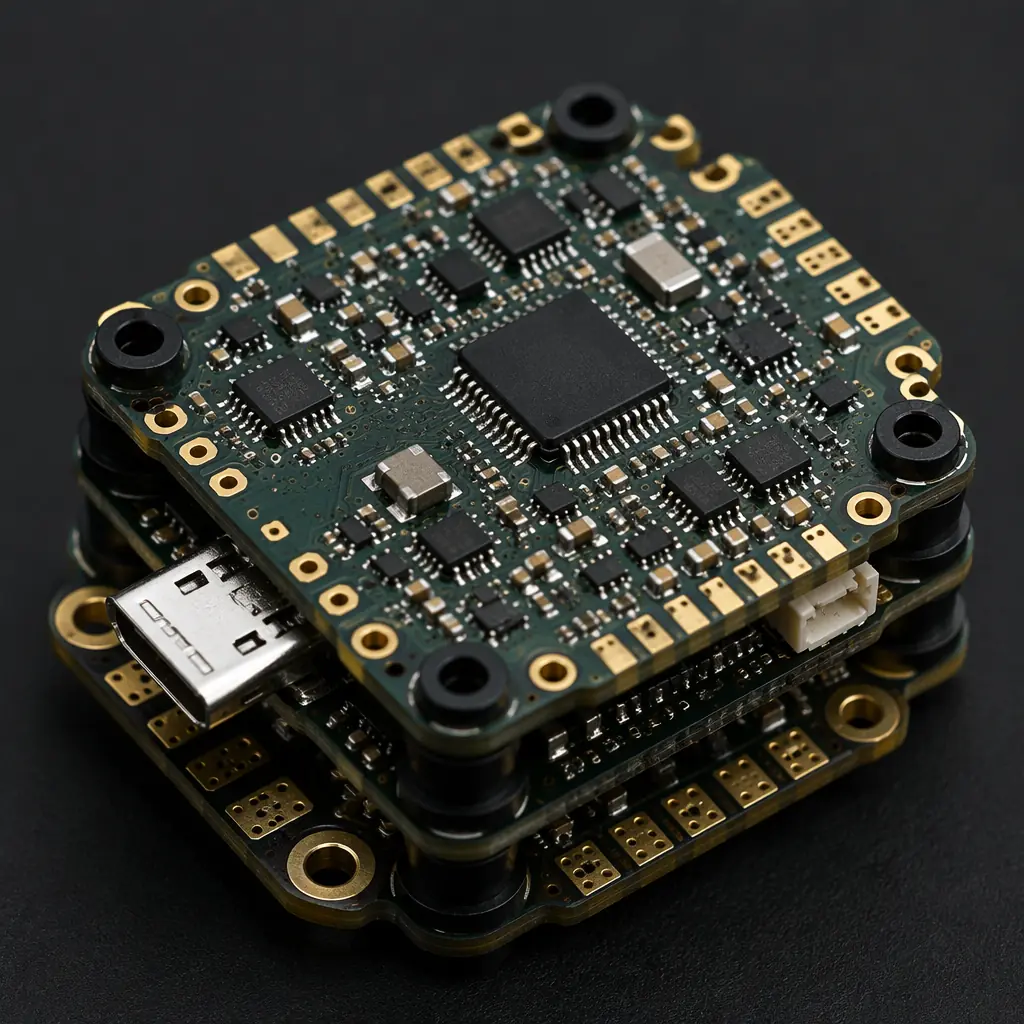
The commercial drone market is projected to exceed $57 billion by 2030, spanning agriculture, logistics, surveillance, and inspection. Every UAV, from a compact quadcopter to a fixed-wing survey platform, depends on densely packed, lightweight PCB assemblies that survive constant vibration, temperature swings, and altitude pressure changes. Getting the PCB specification right directly determines flight endurance, payload capacity, and mission reliability.
At Huaxing PCBA, we manufacture HDI PCBs for drone applications with 0.075 mm microvia capability, 0.4 mm pitch BGA support, and rigid-flex integration, all backed by IPC Class 3 quality standards. This article covers the material, design, and assembly requirements that separate a mission-ready drone PCB from one that fails mid-flight.

Why Drone PCBs Demand a Different Specification
Drone electronics face a unique combination of constraints that consumer and industrial PCBs rarely encounter simultaneously. The four core challenges are:
Weight: Every Gram Costs Flight Time
A typical multi-rotor drone loses 30-60 seconds of flight time for every additional 10 grams of payload. PCB substrate selection, thinner FR-4, polyimide flex layers, or hybrid rigid-flex, directly impacts endurance. Our rigid-flex PCB manufacturing guide covers material trade-offs for weight-sensitive designs.
Vibration, Motor Harmonics Across the Entire Assembly
Four to eight brushless motors generate harmonic vibration from 50 Hz to 2 kHz depending on RPM, transmitted directly through the airframe. BGA solder joints, ceramic capacitors, and connector pins all see cyclic stress. Our PCB crosstalk and mechanical stress analysis explains via fatigue mechanisms relevant here.
Thermal Cycling, From Ground Heat to Sub-Zero Altitude
A drone climbing from 35°C ground temperature to -15°C at 400 m altitude in under 60 seconds creates rapid thermal gradients. CTE mismatch between PCB laminate and components causes solder joint micro-cracking over repeated flights. See our PCB thermal management guide for material selection strategies.
Space Constraints, 6-Layer Routing in 40×40 mm
Flight controller boards often measure under 40 × 40 mm yet must route IMU, barometer, compass, GPS, ESC signals, and power distribution. HDI microvia technology with stacked vias becomes mandatory. Our HDI PCB technology guide covers when to upgrade from through-hole to microvia design.
Key Takeaway: Drone PCBs are not just "smaller industrial PCBs." They require simultaneous optimization of weight, vibration resistance, thermal endurance, and routing density, a four-way trade-off that generic PCB specifications fail to address.
Material Selection for UAV Electronics
The laminate choice determines the weight-vs-reliability baseline. For drone applications, three material families dominate:
| Material | Typical Thickness | Weight (g/cm²) | Best For |
|---|---|---|---|
| FR-4 (Standard Tg 130°C) | 0.4 – 0.8 mm | 0.08 – 0.14 | ESC boards, power distribution, non-flight-critical |
| FR-4 (High-Tg 170°C) | 0.3 – 0.6 mm | 0.06 – 0.11 | Flight controllers, IMU boards with dense BGA |
| Polyimide Flex / Rigid-Flex | 0.1 – 0.3 mm | 0.03 – 0.06 | Gimbal interconnect, foldable arms, payload flex circuits |
| PTFE / Hydrocarbon Ceramic | 0.25 – 0.5 mm | 0.05 – 0.10 | mmWave radar altimeter, 5.8 GHz video downlink RF sections |
For most commercial drone flight controllers, we recommend 0.4 mm high-Tg FR-4 with 6-layer HDI stackup, this delivers the best weight-to-reliability ratio at production volumes of 1,000+ units. For payloads requiring GHz RF performance, refer to our RF PCB design and manufacturing guide for material selection above 2 GHz.
Vibration Mitigation in PCB Design
Motor vibration is the leading cause of drone PCB field failures, accounting for an estimated 40-55% of in-service electronics issues according to UAV fleet operators we work with. The failure modes are progressive: initial micro-cracks in solder joints grow with each flight cycle until an intermittent open circuit appears, including often mid-mission.
Stiffener Plates Under Large BGAs and QFNs
Adding a 0.2 mm FR-4 or aluminum stiffener under the flight controller's main processor BGA shifts the board's natural frequency above the motor excitation range. This is particularly critical for IMU sensor packages, where vibration-induced noise directly degrades attitude estimation accuracy.
Via-in-Pad with Copper Fill for High-Stress Nodes
Standard dog-bone fanout vias create stress concentration points under repeated vibration. Via-in-pad with copper-filled conductive epoxy eliminates the stress riser and improves thermal conductivity for power components like ESC MOSFETs.
Corner Mounting Hole Reinforcement
Drone PCBs are typically mounted at four corner points with M2 or M2.5 standoffs. We recommend 3 mm diameter plated mounting holes with annular ring reinforcement and no traces within 2 mm of the hole edge, this prevents trace cracking from frame-transmitted vibration.
Conformal Coating for Humidity and Dew Point Protection
Agricultural drones operate in high-humidity environments with frequent dew-point crossings. Acrylic or silicone conformal coating at 25-50 μm thickness protects against moisture ingress without adding meaningful weight.
Procurement Tip: When sourcing drone PCBs, specify IPC Class 2 as the minimum standard but request Class 3 for all plated through-holes. The incremental cost is typically under 8% but eliminates the #1 field failure mode, barrel cracking from vibration fatigue. See our IPC Class 2 vs Class 3 comparison for the full breakdown.
HDI Routing for Compact Flight Controllers
Modern drone flight controllers integrate IMU, barometer, magnetometer, GNSS receiver, and multiple UART/SPI/I²C peripherals on a single board. Routing all of this within a 36 × 36 mm footprint requires HDI microvia technology with careful layer stackup planning.
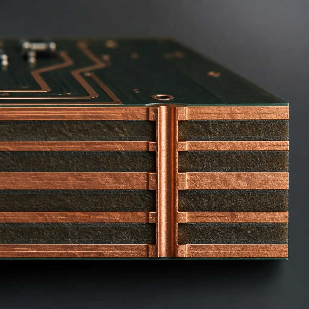
A typical 6-layer flight controller stackup we manufacture for commercial drone OEMs:
| Layer | Function | Technology |
|---|---|---|
| L1 (Top) | Components + short signal routes | 0.075 mm µvia to L2 |
| L2 | Ground plane (solid) | Buried via to L3/L5 |
| L3 | High-speed signal routing (SPI, UART) | 0.1 mm µvia stack |
| L4 | Power distribution (3.3V, 5V, VBAT) | 0.1 mm µvia stack |
| L5 | Ground plane (solid) | Buried via to L2/L3 |
| L6 (Bottom) | ESC signal pads + auxiliary connectors | 0.075 mm µvia to L5 |
This stackup achieves 0.4 mm total thickness (including solder mask), weighs approximately 1.2 grams for a 36×36 mm board, and supports 0.4 mm pitch BGA packages. For higher-density designs, our PCB stackup design guide covers 8- and 10-layer options.
Assembly Considerations for Drone Production Volumes
Drone PCB production spans prototyping (10-50 units), pilot runs (100-500 units), and mass production (5,000-50,000 units/year). Each phase demands a different assembly strategy:
Prototype Phase, Quick-Turn with Full DFM
Our quick-turn PCB service delivers functional prototypes in 5-7 days with free DFM review. We check via-in-pad fill, solder mask clearance under 0.4 mm pitch BGAs, and impedance tolerances before fabrication begins.
Pilot Production, Panel Optimization
For 100-500 unit runs, PCB panelization optimization becomes the dominant cost driver. We nest flight controller, ESC, and power distribution boards on shared panels with V-score separation to maximize material utilization.
Mass Production, Automated AOI and Functional Test
At 5,000+ units/year, automated AOI inspection and functional testing become mandatory. We deploy flying-probe ICT for prototype validation and bed-of-nails functional test fixtures for volume production, including IMU calibration verification.
At Huaxing PCBA, we support drone OEMs across the full product lifecycle, from first prototype through sustained volume production. Our 8 SMT lines handle 0201 passive components, 0.4 mm pitch BGAs, and mixed rigid-flex assemblies. For a project-specific consultation, contact our engineering team with your stackup requirements.
