

"Is the coating under the component?" is the most common coating question a quality engineer is asked after an audit, and it is usually answered with an opinion rather than a measurement. The honest answer is that it depends on the gap between the component body and the board, on the viscosity and surface energy of the coating, and on how the coating was applied. Under a stand-off of about 0.05 mm nothing is going to creep in except a very low-viscosity material applied with a dwell, and under a relay or a connector the correct answer is that coating should not be there at all.
This page sets out the capillary mechanism that decides penetration, the gap heights at which each chemistry stops moving, a package-by-package verdict including the cases where coating under the part is a defect rather than a benefit, and the destructive tests that turn the answer into evidence.
Capillary Creep: The Mechanism
Coating reaches under a component by capillary action, the same mechanism that pulls water up a narrow tube. In a capillary, the driving pressure is the surface tension of the liquid times the cosine of its contact angle with the wall, divided by the gap. Two things follow directly. A smaller gap gives a stronger driving pressure, but also a much greater flow resistance, and the resistance wins: below a certain gap the liquid simply cannot travel far enough in the time available before it cures or the board moves on.
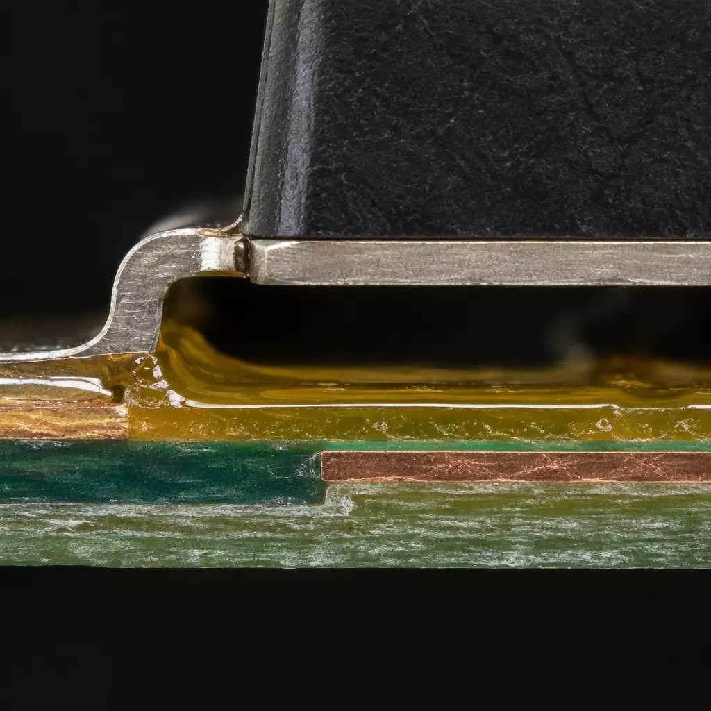
The fillet at the component edge is where creep starts. Whether it continues under the body is a capillary question, not a spraying one.
Three variables matter more than the rest. Viscosity sets the resistance: a low-viscosity acrylic flows into a 0.1 mm gap readily, a thixotropic silicone barely moves. Surface energy of the substrate sets the contact angle: a clean laminate with a fresh mask wets well, a surface with flux residue or release agent does not, and a poor wetting angle can stop creep entirely at gaps that would otherwise fill. Dwell time sets how far the liquid gets: a dip or a flood coat with a long dwell penetrates further than a single spray pass, because the material has minutes rather than seconds to move.
The fourth variable is geometry, and it is the one buyers underestimate. Creep does not need to travel far to be judged a failure: on a 5 mm body, penetration of 1 mm past the edge reads as "coating under the part" in a photograph and as "no coverage" in a cross-section taken at the centre. Both observations are correct, and the difference between them is what makes the audit argument so difficult.
Gap Height Is the Gate
The gap between the bottom of the component body and the top of the board is set by the lead form or the stand-off, and it is the single best predictor of whether coating will reach under. The table below gives the penetration we expect in a 60-second dwell for the three common chemistries, on a clean board with good wetting. The figures are observations from our own lines, not guarantees, and the point is the shape of the curve rather than the exact values.
| Gap under body | Acrylic, low viscosity | Polyurethane | Silicone | Practical verdict |
|---|---|---|---|---|
| 0.50 mm and above | Full coverage | Full coverage | Most of the footprint | Under-body coverage is achievable and testable |
| 0.20 mm | Full coverage | Most of the footprint | Edge fillet only | Depends on chemistry, specify the test |
| 0.10 mm | Most of the footprint | Edge fillet only | Edge fillet only | Do not promise central coverage |
| 0.05 mm | Edge fillet only | None | None | Treat as not coatable underneath |
| Below 0.05 mm | None | None | None | Answer is no, in any chemistry |
The 0.05 mm row is the one to remember. Below it, the gap is roughly the same order as the particulate contamination the board will carry, and the capillary path is blocked by things that are not the coating: dust, mask ridges, solder resist dams, stray solder balls. A supplier who promises full under-body coverage at a 0.04 mm stand-off is promising something the physics does not support, and the promise will be tested by a cross-section at some point.
Gap height is also not uniform. A gull-wing lead holds the body a nominal distance off the board, but the mask thickness under the body varies, the laminate may have a slight bow, and the body itself is not perfectly flat. A design specified at 0.10 mm frequently presents 0.06 mm at one corner and 0.15 mm at the other, and the coating follows the geometry rather than the drawing. That is why the penetration question should be answered per package position rather than per assembly.
Package by Package: Where Coating Should and Should Not Go
Coating under a component is not universally desirable. On some packages it protects; on others it creates a failure. The verdict below is the useful form of the answer, because it lets a quality engineer reply to an audit question with a position rather than a shrug.
A gull-wing SOIC or QFP with a 0.10 mm to 0.20 mm stand-off benefits from creep. The gap is large enough for the material to travel, the leads are the corrosion-sensitive feature, and coating that reaches the lead root protects the joint that matters. Here the specification should ask for coverage at the lead root rather than under the body centre, and the acceptance photograph should be taken from the side.
A QFN with an exposed thermal pad is the opposite case. The pad must remain solderable and the coating must not enter the gap between the body and the pad, because material under a QFN cannot be inspected and its thermal expansion during reflow of a subsequent process can lift the part. Coating on a QFN should stop at the body edge, and the exposed pad is a keep-out that must be masked, not a coverage target. Our page on QFN and LGA leadless package soldering covers the assembly side of the same geometry.
A BGA is a third case again. Capillary creep will travel into the ball field at gaps around 0.3 mm to 0.5 mm, and it will not reach the die. Coverage of the outer ball rows is achievable and worth having on a harsh-environment board, but the material that creeps into the ball field also changes the thermal and mechanical environment of the joints, and it makes rework of an inner ball effectively impossible. If the programme expects BGA rework, the coating should be confined to the perimeter and the rework path should be written into the process before the first build.
Connectors, relays and any component with moving contacts are a definite no. Coating that creeps into a contact interface is a defect: it insulates the contact, it attracts and traps debris, and on a relay it can glue the armature. Masking these parts is not an optional refinement, it is the difference between a conforming assembly and one that fails at first operation. The keep-out geometry and the methods that hold it are set out in conformal coating masking.
Why Buyers Get Asked This, and What the Standards Actually Say
The question usually arrives from a customer's quality function, phrased as a requirement that coating be continuous over the assembly. The requirement is real, but continuity has a scope: it applies to surfaces the process is intended to coat, and it is assessed against acceptance criteria that distinguish voids, bubbles and dewetted areas from the absence of coverage in a place where coverage was never expected.
The practical reading is that a supplier should never claim universal coverage, and should instead document the coverage intent per region of the board. That is the position that survives an audit, because it is verifiable at every point: a keep-out that is masked and clean is obviously conforming, a lead root with a visible fillet is obviously conforming, and a claim of coverage at the centre of a 0.04 mm gap is obviously not. The acceptance language that applies to each of these is set out in IPC-A-610 coating acceptance, which also covers the class differences that decide how much of a void is tolerated.
Written into the purchase order, the requirement should name the regions. Coating continuous over the lead roots of J1 to J4; no coating on the exposed pads of U7 and U9; no coating on connector contacts; coating coverage to be verified by UV tracer on the first article and by cross-section at one position per lot. That is five lines, it is testable, and it removes the ambiguity that produces the audit finding in the first place.
Measurement: Proving It Rather Than Asserting It
Three methods answer the coverage question, at three different costs, and only one of them survives a cross-section.

A cross-section is the only method that shows what is under the body. UV tracer shows what fluoresces, which is not the same question.
UV tracer inspection is fast, non-destructive and cheap, and it answers "did the material reach this region". It is the right tool for routine coverage checks and for the first article. Its limitation is that it shows the surface, and a coating that has wicked into a gap but not filled it will still fluoresce at the entrance. On a UV tracer coverage check the finding is usually correct at the region level and silent at the gap level.
Cross-sectioning is destructive, slow and definitive. A section through the component body shows the gap, the fill, the voids and the interface, and it is the only evidence that settles an argument with a customer's quality engineer. The cost is one assembly per section position per lot, plus the preparation time, which is why it belongs at first article and at a periodic interval rather than on every build.
Dye penetration sits between the two. A coated assembly is immersed in a fluorescent dye that penetrates any gap the coating failed to fill, then sectioned or inspected under UV. It is more sensitive than plain UV inspection to incomplete fill and less expensive than a full section series, and it is the method we reach for when a customer asks for coverage evidence on a package whose gap height sits right at the threshold.
Process Levers When the Answer Has to Be Yes
When a design genuinely needs material under a body, the lever is not more spray. Spray deposits on the top surface and its penetration is limited by the same capillary gate as everything else. The levers that work are the ones that change the liquid's ability to move: a lower-viscosity material within the same chemistry family, a longer dwell before cure, pre-heating the board so the material wets and flows before its viscosity rises, and dispensing rather than spraying at the component edge.
The other honest lever is to change the process rather than the coating. Potting fills the volume rather than wetting the surface, and where full encapsulation is acceptable it answers the under-body question completely. Selective coating with a dispense pass at the package edge answers it partially and cheaply. Both are cost decisions as much as engineering ones, and the trade-off is laid out in selective conformal coating cost and in the comparison of coating chemistries.
The one thing that does not work is specifying a thickness at the top surface and assuming it implies coverage underneath. Thickness is measured where the coating is thickest and easiest to measure, which is almost never the gap under a component. Our thickness control page covers why the measurement methods disagree before the under-body question even arises.
At Huaxing PCBA the coating intent is written per region on the assembly drawing, UV tracer on the first article confirms that the material reached the regions that need it, and cross-sections at the agreed positions provide the under-body evidence. If your customer has raised the "coating under the component" question and the answer is currently a verbal one, send the assembly drawing and the component list through the quote form and we will return a region-by-region position you can put in writing.