
PCB Types / Rigid-Flex PCB
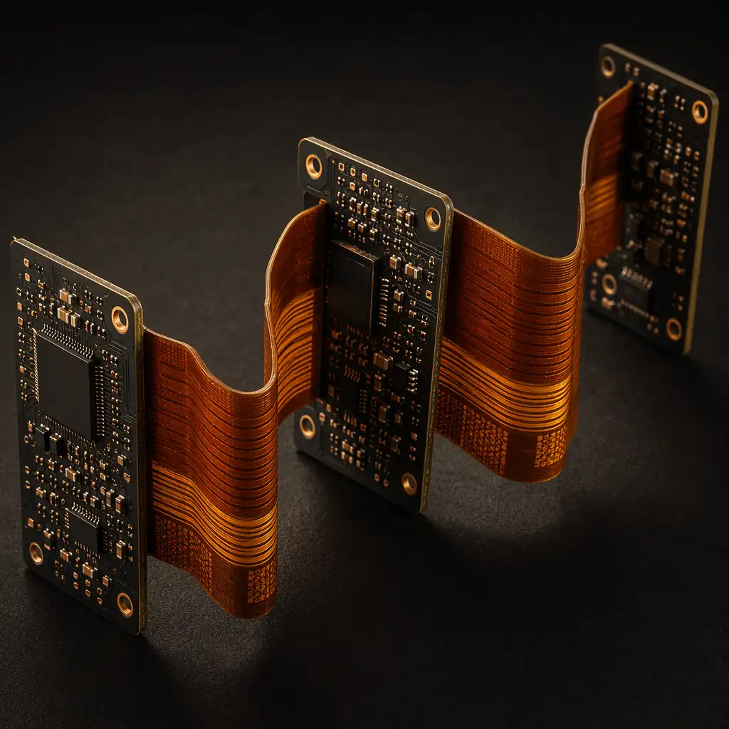
Rigid-flex PCBs combine rigid FR-4 sections with flexible polyimide layers in a single unified construction, eliminating connectors, reducing assembly steps, and enabling 3D packaging that saves weight and space. Up to 10 rigid + 4 flex layers, IPC 6013 Type 4 certified.
Technology Overview
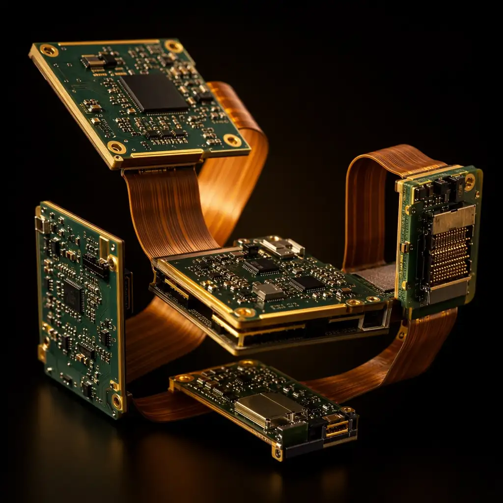
Rigid-flex PCBs are hybrid constructions where rigid FR-4 sections and flexible polyimide layers are manufactured as a single inseparable board. The rigid sections hold components and connectors; the flex sections fold to fit into tight 3D enclosures, replacing board-to-board connectors, ribbon cables, and wire harnesses.
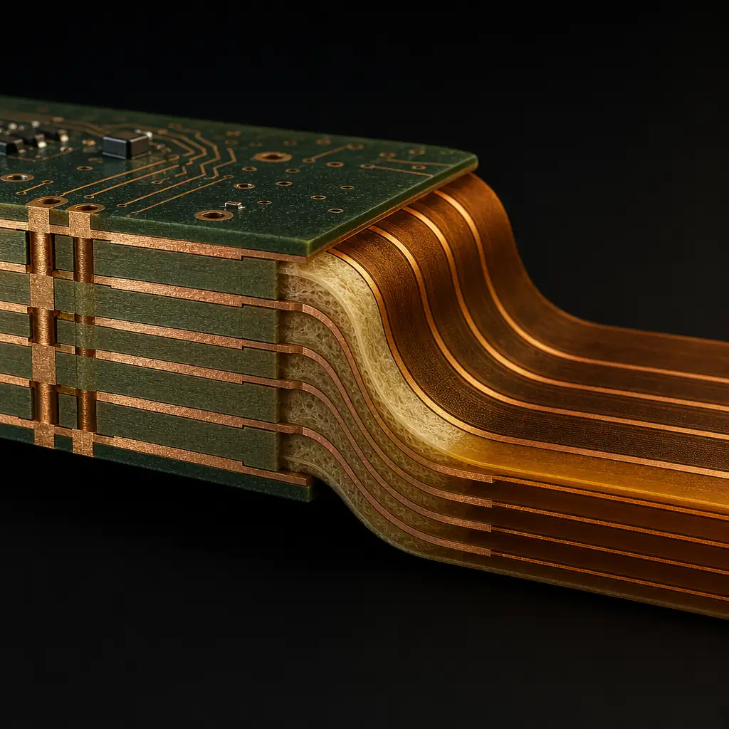
Key to rigid-flex manufacturing is the transition zone, where rigid layers end and flex layers continue. No-flow prepreg prevents resin from bleeding into the flex area during lamination, and specialized coverlay materials protect exposed flex traces. Our process supports both bookbinder (continuous flex) and air-gap (separated rigid sections) configurations.
Technical Specifications
| Maximum Configuration | 10 Rigid + 4 Flex layers; custom eval for more complex builds |
| Rigid Materials | FR-4 · High-Tg FR-4 (170/180°C) · Halogen-Free · Rogers (hybrid RF rigid-flex) |
| Flex Materials | Polyimide 25/50/75µm · Adhesiveless or adhesive-based · LCP option |
| Min. Trace / Space | 3 / 3 mil (flex section); 3.5 / 3.5 mil (rigid section) |
| Min. Mechanical Drill | 0.2 mm (rigid); 0.15 mm (flex) |
| Min. Annular Ring | 4 mil (mechanical); 3 mil (laser microvia) |
| Surface Finish | ENIG · ENEPIG · Immersion Ag · OSP · HASL (rigid sections only) |
| Solder Mask | Green / Black / Blue on rigid sections; coverlay on flex sections |
| Impedance Control | ±5% rigid section; ±7% flex section; TDR report included |
| Stiffeners | FR-4 · PI · Stainless Steel (flex-only areas requiring reinforcement) |
| Quality Standard | IPC-6013 Type 4 Class 2 / Class 3 · IATF 16949 · ISO 9001 |
The most common configuration: rigid sections are like pages of a book bound by a continuous flex layer. No connectors between rigid areas, just fold along the flex. Ideal for 2-4 rigid sections in a compact 3D volume.
Rigid sections are physically separated by an air gap, connected only by flex bridges. Allows independent mechanical mounting of each rigid section. Common in aerospace and defense applications requiring shock/vibration isolation.
HDI microvia technology applied to the rigid portions of a rigid-flex board. Enables fine-pitch BGA on rigid sections while maintaining flex interconnect capability. Used in smartphone main boards and advanced military modules.
Flex layers extend beyond the rigid board outline as ZIF connector tails with gold-plated contact fingers. Eliminates a separate connector purchase and assembly step. Standard 0.3-1.0mm pitch ZIF supported.
Manufacturing Process
The critical step in rigid-flex manufacturing is lamination, bonding rigid FR-4 to polyimide flex without contaminating the flex area with epoxy resin. We use no-flow prepreg with precisely controlled resin content and a specialized press cycle that cures the rigid stack while protecting the flex transition zone.
Satellite bus interconnects, avionics LRU replacement
Main board + sub-board interconnect, antenna flex
Pacemaker circuits, cochlear implants, neurostimulators
ECU interconnect, battery management flex, radar sensor
DSLR sensor board, drone gimbal camera interconnect
Probe card rigid-flex, ATE interface boards
Our engineering team reviews rigid-flex designs daily. Upload your stack-up with rigid and flex layer counts, bend areas, and any special transition requirements. Free DFM within 24 hours.

Tell us rigid+flex layer counts, configuration, BGA pitch, quantity. Free DFM review.