
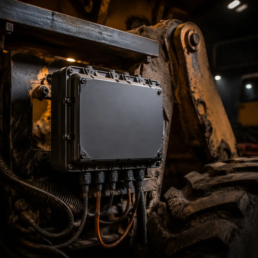
An electric mining truck idling at the pit face has no warm, dry, vibration-free cabinet. The control board bolted to its frame is dust-coated, moisture-laden, thermally cycling and hammered by continuous vibration for every hour of every shift. When that board fails, the whole machine stops. And a stopped haul truck, drill or conveyor burns downtime at a rate that makes the price of the board irrelevant.
The most expensive failure in mining electronics is not a catastrophic short. It is the intermittent one: a connector that loosens, a solder joint that cracks, a trace that corrodes under ore dust and condensation. These are not random. They are predictable consequences of spec'ing a board as if it were sitting in a server rack. At Huaxing PCBA, we run mining and heavy-equipment boards through the same lines that produce our harsh-environment reliability work, 8 SMT lines and 4 DIP lines backed by 32-layer capability. And they only ship after the environmental tests below are documented. This guide is the framework we use with OEMs to keep those machines running.
The Harsh Environment: Dust, Moisture, Temperature & Vibration
Every mining environment is a hostile environment, but the failure mechanisms it throws at a PCB are not actually mysterious. Three stressor groups do most of the damage, and each one attacks a different part of the board:
| Stressor | What it does | Typical mining condition | Design response |
|---|---|---|---|
| Abrasive dust | Insulates contacts, blocks heat dissipation, promotes arcing on bare traces | Ore dust, coal fines, silica | Conformal coating, sealed IP-rated housings, potted connectors |
| Moisture & condensation | Electrochemical migration, corrosion of exposed copper, dendrite growth | Humidity and water spray underground, open-pit rain | Thick conformal coating, encapsulation, corrosion-resistant finishes |
| Wide temperature swings | Coefficient of expansion mismatch, solder fatigue, drift in components | From below-freezing nights to engine-compartment heat | Component derating, matched CTE board materials, thermal management |
| Vibration & shock | Fretting on connectors, cracked solder joints, broken component leads | Continuous machine vibration, drop and impact loads | Reinforced mounting, strain relief, potting, structural support |
The temperature envelope is a good place to start when you specify a board. A surface-mount controller in an industrial cabinet might only need to cover 0 °C to +50 °C. A mining board has to survive -40 °C to +85 °C as a baseline, and +105 °C when it sits inside an engine compartment or near a hydraulic pump. That single decision cascades into component choices, solder alloy, thermal copper pours and whether you need active cooling. For the broader reliability strategy behind these choices, our industrial control board guide covers the same discipline in a different application.
Design Rules for Rugged Mining PCBs
Ruggedizing a board is a set of deliberate choices, not a coating at the end. These are the design rules we push on every mining program before a single layer is fabricated.
Derate components well inside the limits
Never run a resistor, capacitor or IC at its maximum rated temperature. Derating is what protects you when ambient hits the top of the range, not the datasheet ceiling. This is where most early field failures start.
Heavy copper for the power paths
High-current traces carrying motor drive and pump currents need thicker copper to reduce heating and keep the trace secure under thermal cycling. See our heavy copper for high current guide for the stack-up tradeoffs.
Reinforced mounting and strain relief
Oversize the mounting holes, add standoffs, and never rely on a connector to carry mechanical load. Every connector should be backed by a strain relief that keeps the wire and the solder joint from fretting.
Pot vulnerable components
Through-hole and heavy components that would resonate at machine vibration frequencies are the first to crack. Encapsulation or targeted potting locks them rigid so they cannot flex. We detail the materials in our potting and encapsulation guide.
Keep board size rigid, not flexible
Large boards flex under shock. Strictly size the board to the enclosure, and avoid any design that leaves a large span unsupported between mounting points.
Plan the testing up front
Vibration, thermal and sealing tests are not a validation afterthought, they are the acceptance criteria. Decide the standard (typically IEC 60068-2) before you commit to a supplier, not after the sample arrives.
Engineering Note: The single highest-value ruggedization step is usually not exotic. It is the combination of proper conformal coating plus potting of the connectors and heavy components, captured in a documented test plan. If a supplier cannot name the thickness, material and test standard on the coating, they have not ruggedized the board at all.
Conformal Coating, Potting & Encapsulation, the Armor Layer
The armor layer is what physically separates the fragile circuitry from the hostile world. It comes in two main families, and mining boards typically need both: a thin conformal coating over the whole assembly, and a heavier encapsulation or potting over the components that matter most.
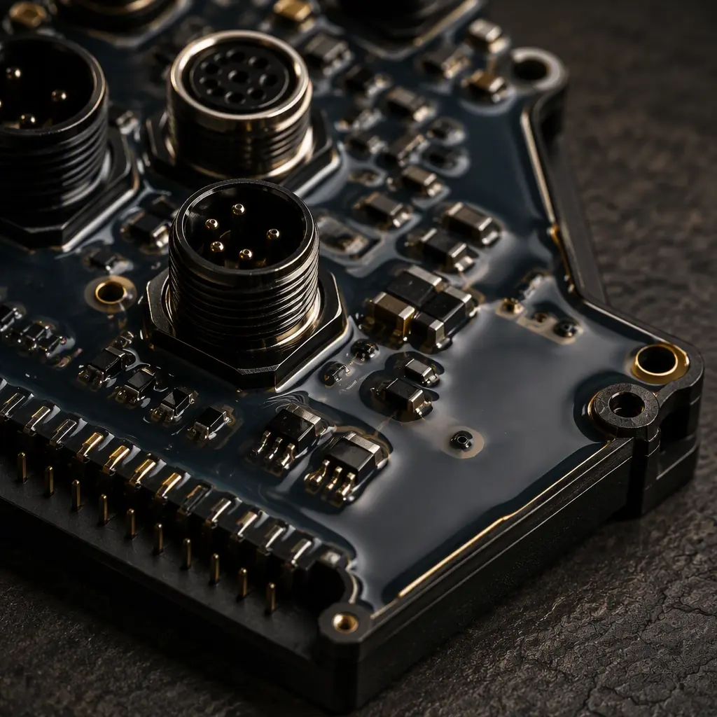
A conformal coating is a thin dielectric film applied over the finished board to block moisture, dust and conductive contamination. The thickness is the variable that decides protection level. For a mining environment you want a substantially heavier coat than a consumer board would carry, roughly 25–75 µm for parylene or 50–100 µm for acrylic or urethane. The appropriate material depends on the sealed enclosure, the temperature envelope and whether the machine sees chemical or solvent exposure. The selection criteria are covered in our conformal coating selection guide.
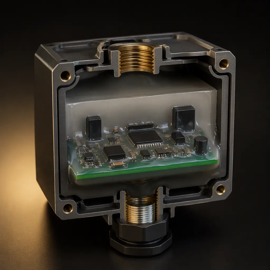
Potting and encapsulation are the heavier sibling. Where conformal coating protects the full surface thinly, potting fills a cavity or covers a component with a solid compound, silicone, polyurethane or epoxy, that locks the assembly rigid and seals it against moisture and dust. This is the defense against the specific failures mining sees most: a cracked heavy-component solder joint, or a connector that corrodes from condensation. It also adds mechanical rigidity so vibration cannot flex the board and fracture leads.
Key Takeaway: Coating protects the surface; potting protects the stress points. A truly rugged mining PCB uses a thick conformal coating across the whole assembly and targeted potting or encapsulation over connectors, power components and anything heavy enough to resonate. Ask the supplier to state the material and dry-film thickness on the print, because that is what you will test against.
Enclosures, Connectors & Sealing, IP-Rated Hardware
A coating will not save a board whose enclosure lets ore dust in. The hardware that surrounds the PCB is part of the reliability story, and the rating you select is the contract with the environment.
| IP rating | Solid protection | Liquid protection | Typical mining use |
|---|---|---|---|
| IP65 | Dust-tight | Low-pressure water jets | Open-pit equipment, dry plant conveyors |
| IP66 | Dust-tight | Powerful water jets | Washdown areas, drills, central plant |
| IP67 | Dust-tight | Immersion up to 1 m for 30 min | Underground machines, pumps, wet conditions |
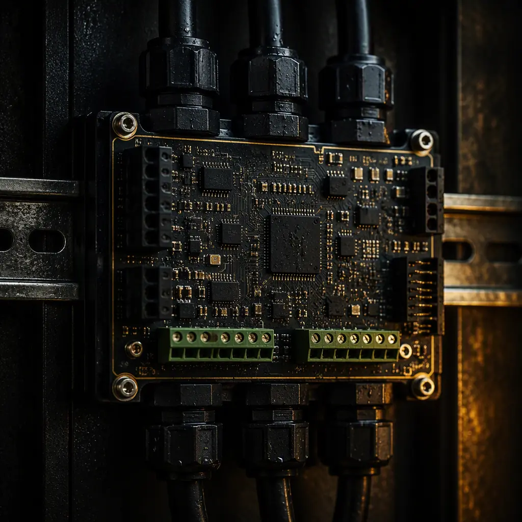
The rating is only as good as the weakest entry point. Two places leak more than any other: the cable gland where wires enter, and the mating connector on the board itself. Use sealed IP-rated connectors with a proper gland, and add a sealing gasket at the lid to keep condensate out. For underground work, this is as important as the board design itself. A dust-tight, gasketed enclosure with IP67-panel connectors is what keeps your IP66/IP67 sealing claims honest. The same logic behind sealing against the elements is what drives our marine-grade PCB approach, where salt and humidity are the enemies.
Vibration, Shock & Thermal Management
Mining machines are, by design, violent. The two environmental standards your board will most often be tested against are IEC 60068-2-64 for continuous random vibration and IEC 60068-2-27 for shock, the same tests we apply in our vibration and shock testing methodology. They are not optional if your machine claims to survive the field.
Vibration kills boards through fretting: the repeated micro-motion that wears away the metal-to-metal contact at a connector or a solder joint. Shock kills them through a single hard flex. The countermeasures are mechanical more than electrical, redundant mounting, stiffening ribs, vias stitched around the mounting point, and potting to damp resonance. Keep heavy components low and close to a mounting point, and never let a tall electrolytic capacitor dangle unsupported.
Heat is the other multiplier. Vibration and thermal stress interact: a board that runs hot is a board whose solder joints and coating degrade faster under the same vibration. Use copper pours to spread heat, keep the high-current power stage on a dedicated thermal zone, and derate components so they never approach their ceiling. When ambient alone can reach +85 °C, every degree you shave off the junction temperature buys back reliability. The design tradeoffs are laid out in our PCB thermal management guide.
Intrinsic Safety, ATEX & Surge Protection
Coal mines and gassy environments add a constraint that dwarfs everything above: the board must not be capable of igniting an explosive atmosphere. This is where intrinsic safety (Ex ia) comes in under ATEX and the IEC-Ex scheme. The concept is that the electrical energy available in the circuit, voltage, current, stored capacitance and inductance, is limited below the ignition threshold of the surrounding gas, so a spark cannot occur with enough energy to ignite it. It is a design discipline as much as a label. The full logic is covered in our intrinsically safe and ATEX design article, linked from this intrinsically safe / ATEX guide.
Electric-drive machines add a second layer of risk. An electric mining truck or a large conveyor runs on drive electronics that see extreme current transients and regenerative surges. These machines need robust surge and transient protection on the power input and at every field interface . Metal-oxide varistors, TVS diodes and proper filtering, so a voltage spike at the motor cannot propagate back into the control board and destroy the low-voltage logic. In a mining environment, the surge is not a rare lightning event; it is a steady fact of industrial power.
Key Takeaway: Two families of risk exist side by side. In a gassy mine the board must be intrinsically safe (Ex ia / ATEX) so it can never ignite the atmosphere. In an electric-drive machine it must be protected against power-line surges and regenerative transients so a spike cannot reach the control logic. If your application has either, the design rules change before the layout even starts.
How to Source a Factory for Mining PCBs
Choosing a factory for a mining board is not the same as choosing one for a consumer product. The RFQ needs to ask questions that separate a shop that sells boards from a shop that has actually ruggedized them. Put these in writing:
Name the coating material and dry-film thickness
Ask for the conformal coating type and thickness in microns, and whether vulnerable components are potted or encapsulated. A vague answer is a red flag.
Demand the environmental test plan and standard
Ask for the IEC 60068-2 vibration and shock test parameters, the IP sealing target and the thermal profile. Confirm whether these tests are run on every lot or only on qualification samples.
Require workmanship acceptance evidence
Ask which workmanship standard the assembly is built to, IPC-A-610 for soldering is the baseline, and whether coating and inspection records ship with the lot.
Confirm the reliability of the supply chain
Ask about the source of the components, the factory's traceability systems and the certifications behind the plant, not just the board. The reliability of a mining board is the reliability of its weakest material.
At Huaxing PCBA the requests above map directly onto how we run the plant. Our 8 SMT lines, 4 DIP lines and 32-layer capability sit inside a 15,000 m² facility with 500+ staff, processing over 8 million placements per day for customers in 30+ countries. Everything runs under a single ISO 9001 and IATF 16949 quality management system, with UL-certified materials and a documented test record for environmental validation.
Summary / Next Steps
Ruggedizing a PCB for mining and heavy-duty equipment is a chain of decisions that starts with the temperature envelope and ends with a documented test plan. The board needs a thick conformal coating, 25–75 µm parylene or 50–100 µm acrylic/urethane. Plus potting of the stress points, an IP-rated enclosure, IEC 60068-2 vibration and shock validation, wide-temperature design, and, where the atmosphere is gassy, an intrinsically safe (Ex ia / ATEX) architecture. Skip any one of those and you are shipping a board that the environment will find.
If you are sourcing a control board for a drill, load-haul-dump, conveyor, pump, ventilation system or electric mining truck, send us your schematic and BOM. We will come back with a DFM review, a ruggedization plan and a written environmental test plan within 24 hours. Upload your files for a quote or talk to our engineering team about your mining and heavy-equipment specification.
