Laminate selection is usually argued on electrical properties, and on high-speed or RF designs it should be. But on the majority of industrial, automotive, medical and consumer boards, the laminate decision is made on thermal and mechanical grounds and then priced by procurement, and the two conversations rarely meet. The result is either a board that pays twice for electrical performance it never uses, or a board that is cheap to buy and expensive to own because a material property was assumed rather than specified.
The property side of this decision, including Tg, Dk, Df, CTE and thermal conductivity across FR-4, High-Tg, Rogers-type hydrocarbon laminates, PTFE, aluminium and polyimide, is covered in the PCB materials guide. This page is the other half: what each family actually changes in fabrication and in service, what the cost delta is per square metre and per panel, what the supply side does to your schedule, and what it costs when the choice turns out to be wrong.
What Actually Changes When You Change Laminate
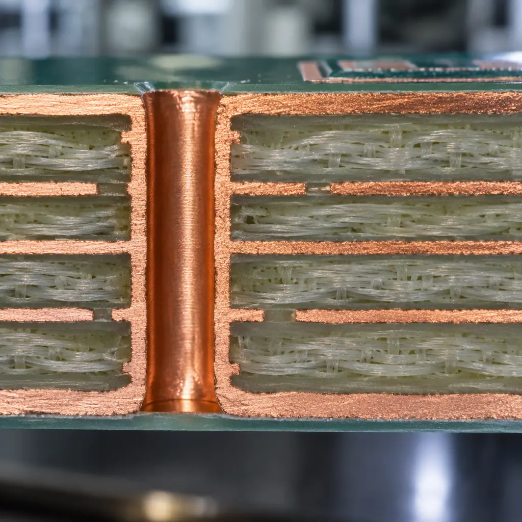
The dielectric is the part of the stackup nobody specifies precisely. It is also the part that decides how the holes, the impedance and the thermal path behave.
Six properties matter, and only two of them are primarily electrical. The rest are thermal and mechanical, and they are the ones that decide whether a stackup is manufacturable at the yield you need.
Glass transition temperature, Tg, is the point at which the resin changes from a glassy to a rubbery state. Standard FR-4 sits around 130 to 140 degrees C, mid-Tg material around 150 to 160, and High-Tg around 170 to 180. The number matters because the board passes through reflow at 245 to 260 degrees C, which is well above every one of those figures, so what actually governs behaviour is the decomposition temperature and the z-axis expansion at reflow, not Tg alone. Tg is a useful proxy: material that begins to soften at 140 degrees C expands more through the thickness at reflow, which stresses the barrel of every plated through hole.
Decomposition temperature, Td, is the point at which the resin loses 5 percent of its mass. It governs how much thermal margin the material has before it starts to char or delaminate, and it is the number that matters on thick boards, on boards that will be reworked, and on boards that will see multiple reflow cycles from double-sided assembly.
Coefficient of thermal expansion in the z-axis, CTE-z, is the mechanism behind most via failures. Copper expands at roughly 17 parts per million per degree C and laminate expands at 40 to 70 depending on the material and the temperature. Above Tg the difference widens sharply, so the barrel of a plated hole is stretched at every reflow and every thermal cycle. Thin boards with high layer counts and small holes have the least barrel length to distribute that strain, which is why a 1.6 mm six-layer board tolerates a laminate that a 0.8 mm twelve-layer board cannot.
Dielectric constant and loss tangent set impedance and insertion loss. For digital designs below about 5 Gbps, standard FR-4 is adequate and the dielectric constant variation between laminate suppliers is a bigger risk than the nominal value. Above that, and certainly at 10 Gbps and beyond or on any RF path, the loss tangent becomes the deciding property, and the choice moves to a low-loss laminate.
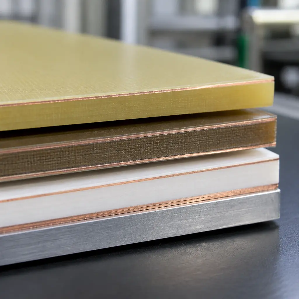
Thermal conductivity decides whether heat moves through the board or stays in the component. Standard FR-4 is a poor conductor, around 0.3 watts per metre-kelvin, which is why thermal vias and copper planes are used to build a parallel path. Materials designed for heat, including metal-core and ceramic-filled laminates, change that by an order of magnitude or more, and the design consequences are covered in aluminium and metal-core PCB design.
Standard FR-4, High-Tg, and The Gap In Between
The most common purchasing question on this topic is whether High-Tg is necessary. The honest answer is that it is mandatory in fewer cases than suppliers imply and pointless in fewer cases than buyers hope.
High-Tg becomes close to mandatory when the board is lead-free and thick, because the combination of a 260 degree C reflow and a long plated barrel produces the highest z-axis strain. It is mandatory on boards that will be reworked, because each rework cycle adds thermal exposure. It is mandatory in automotive under-hood and in any assembly that sees repeated thermal cycling in service, because the fatigue life of the via barrel is a function of how far the laminate expands per cycle. It is prudent on boards with a high layer count relative to thickness, for the same reason.
High-Tg is largely insurance, and reasonably priced insurance, on thin consumer boards assembled once at a competent supplier. The material costs more per square metre, but the delta on a four-layer 1.6 mm board is small in the context of the finished assembly, and the resistance to handling damage during rework and repair is real. Buyers who specify High-Tg across a consumer product line are buying margin against a process they do not control, which is defensible.
Mid-Tg material exists precisely for the gap between those two positions, and it is under-specified in most purchase orders. It provides most of the reflow margin of High-Tg at a smaller cost delta, and on a board that is lead-free but thin, it is often the correct answer. The problem is that the specification is loose: "High-Tg FR-4" without a Tg value, a Td value and a CTE figure allows a supplier to substitute material that meets the words and not the intent. Specify numbers, or expect substitution.
| Material class | Tg (C) | Td (C) | Dk at 1 GHz | Relative material cost | Where it is the right answer |
|---|---|---|---|---|---|
| Standard FR-4 | 130-140 | 310-320 | 4.3-4.6 | 1.0 (baseline) | Thin consumer boards, single reflow, cost-driven |
| Mid-Tg FR-4 | 150-160 | 330-340 | 4.4-4.7 | 1.1-1.3 | Lead-free, thin boards, one or two reflows |
| High-Tg FR-4 | 170-180 | 340-360 | 4.4-4.8 | 1.2-1.6 | Thick boards, high layer count, rework, automotive |
| Low-loss hydrocarbon | 170-200 | 360-390 | 3.3-3.8 | 3-6 | Above 10 Gbps, RF front ends, backplanes |
| PTFE | 200+ | 400+ | 2.2-3.0 | 6-10 | Millimetre wave, low-loss RF, antenna substrates |
| Metal-core (IMS) | n/a (aluminium base) | n/a | 3.5-5.0 | 2-4 | LED arrays, power modules, thermal-dominated boards |
Those figures are family ranges, not specifications for any particular part number, and they vary by supplier and by thickness. The columns that matter for procurement are the last two, and they are the ones absent from most material datasheets.
RF and High-Speed Laminates: What The Delta Buys
The case for a low-loss laminate is an insertion loss budget. At high frequency the dielectric loss is proportional to the loss tangent, the square root of the dielectric constant and the frequency, so moving from a loss tangent of 0.020 to 0.004 reduces dielectric loss by a factor of five on the same trace geometry. That is the entire engineering case, and it is either needed or not.
It is needed when the channel budget is exhausted by the dielectric. On a long backplane trace at 25 Gbps, a low-loss laminate can be the difference between a link that closes with margin and one that needs retimers. On a short trace at 5 Gbps inside a small enclosure, it is not needed at all, and paying for it is a straightforward waste that a competent fabricator should flag. The transition point where the material change becomes cheaper than the alternative remedies, such as additional layers, wider traces or retimers, is the real decision, and it usually sits between 10 and 25 Gbps depending on trace length. Design practice at those rates is covered in 112G and 224G SerDes design and in network switch and router PCB design.
The highest-value technique on mixed-signal boards is not choosing an exotic laminate for the whole board, it is using one only where it is needed. A hybrid stackup puts low-loss material on the outer layers carrying the high-speed or RF traces, with standard FR-4 or High-Tg cores in the middle for mechanical support and power distribution. This captures most of the electrical benefit for a fraction of the material cost, and it is a standard capability rather than an exotic one. The complication is fabrication: mixed materials have different CTE, different drilling behaviour and different dimensional stability, so the fabricator must be competent at bonding them, and the yield penalty is real. The construction and cost trade-offs are set out in hybrid RF laminate stackups.
On pure RF, PTFE dominates the high end and is a different manufacturing problem rather than simply a more expensive laminate. It is soft, it is dimensionally unstable, it is difficult to drill and it requires specialist desmear and plating. The cost delta is not only the material, it is the process discipline, and a fabricator who runs it occasionally will have lower yield than one who runs it weekly. What that discipline involves is covered in PTFE high-frequency PCB manufacturing.
Metal-Core and Ceramic: The Thermal Cases
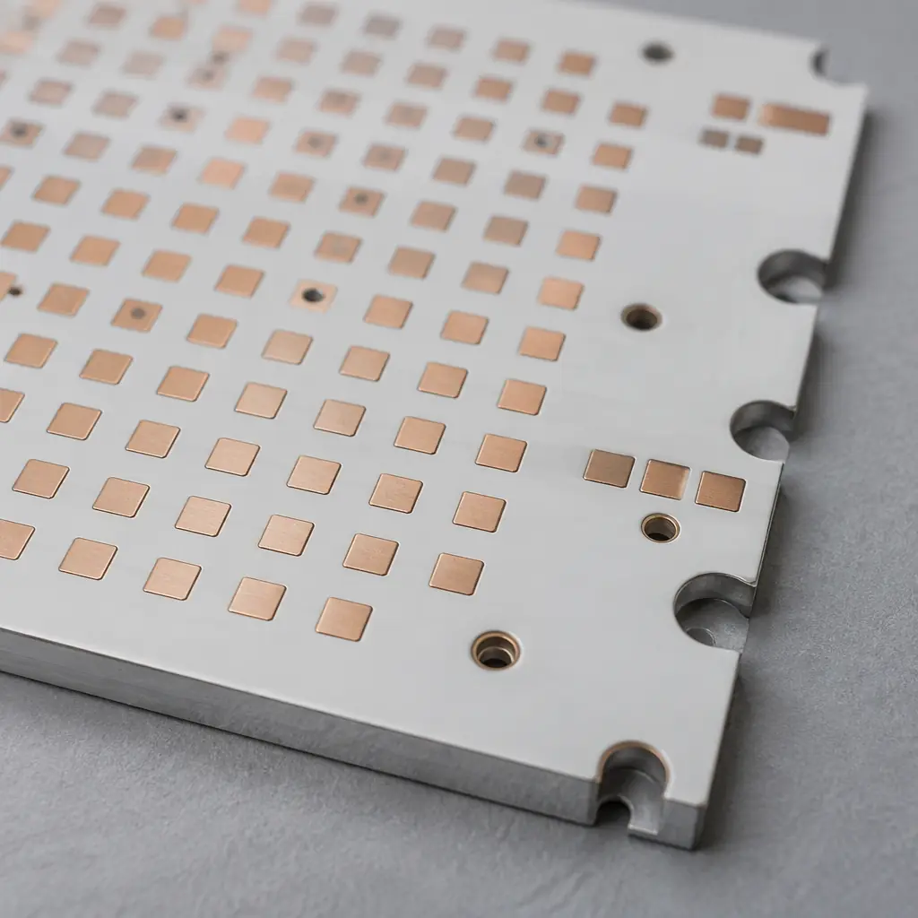
A metal-core board is a thermal solution wearing a circuit board. The dielectric is thin on purpose, and that has consequences for voltage and for routing.
Metal-core boards, usually aluminium with a thin dielectric layer, exist to move heat out of a component and into a heatsink or a chassis. They are the standard answer for LED arrays, power modules and high-current motor drives, where a conventional board would require thermal vias and a thermal interface material to achieve worse results. The material cost is two to four times FR-4, and the design constraints are significant: the dielectric is thin so breakdown voltage is limited, the aluminium cannot be plated through in the normal way so interconnections are usually single-sided or use insulated vias, and the board cannot be routed with standard tooling without care.
The decision to use metal-core is a decision about where the thermal problem should be solved. If the heat can be spread by copper on a conventional board and moved by a heatsink, an FR-4 board with a good thermal path is cheaper and more manufacturable. If the heat density is high enough that the board itself must conduct, metal-core is the correct answer and the price premium is small relative to the alternative of a larger mechanic or an active cooling solution. The selection factors are in the metal-core design guide and the heat path design in thermal via array design.
Ceramic substrates occupy the extreme end: very high thermal conductivity, very high temperature capability, excellent dimensional stability at fine feature sizes, and cost and fragility that rule them out of anything but power and high-frequency applications. They are worth mentioning here mainly to close the loop: the substrate is the most expensive way to solve a thermal problem and the last resort, not the first.
Cost Per Square Metre and Cost Per Panel
Material cost per square metre is what suppliers quote and what buyers compare. It is not what the board costs, because laminate choice changes panel utilisation, drilling behaviour, routing time and yield. The table below adds those effects as a relative index against standard FR-4 at 1.0.
| Material | Material cost index | Panel utilisation effect | Drill and route effect | Typical MOQ | Lead time effect |
|---|---|---|---|---|---|
| Standard FR-4 | 1.0 | baseline | baseline | 1 panel, stocked | baseline |
| High-Tg FR-4 | 1.2-1.6 | none | slightly harder, more tool wear | stocked in common thicknesses | none to +3 days |
| Low-loss hydrocarbon | 3-6 | larger clearance needed, losses rise | slower drilling, specialist desmear | often 1-5 panels minimum | +5 to +15 days |
| PTFE | 6-10 | poor dimensional stability, losses rise | specialist process, lower yield | 1-3 panels, often allocated | +10 to +25 days |
| Metal-core | 2-4 | routing-limited, low utilisation | no standard PTH, punch or route only | 1 panel, thickness dependent | +3 to +10 days |
The panel utilisation column is the one buyers miss. Exotic laminates are often supplied in a restricted range of panel sizes, which reduces the nesting options and can cost 5 to 15 percent of usable area compared with a stocked FR-4 panel in an optimised size. Combined with the higher material index, the effective cost per good board can be well above the material ratio. Panel utilisation mechanics are covered in panel utilisation and nesting, and the stackup decisions that set it in PCB stackup design.
The lead-time column is the one that breaks programmes. A low-loss laminate that is not in stock at the fabricator or the distributor adds two to three weeks to the first build, and if the design changes after the material is ordered, the new order starts the clock again. On a programme with a fixed launch date, the practical question is not whether the material is affordable but whether it is available before the schedule runs out. That risk is worth pricing explicitly, because the cost of a delayed launch is almost always larger than the material delta.
The Cost of Choosing Wrong
Material decisions are cheap to make and expensive to reverse, which is the opposite of most design decisions. Three failure modes carry most of the cost.
The first is under-specifying. A purchase order that says High-Tg FR-4 without a Tg value allows the supplier to use material at the bottom of the range, which on a thick rework-heavy board will fail in thermal cycling after the qualification run has already passed. The cost is a requalification, which on automotive or medical products is the single most expensive engineering activity in the programme.
The second is over-specifying. A low-loss laminate chosen for a design that did not need it adds material cost, adds lead time, reduces panel utilisation and reduces the number of fabricators who can build the board, which reduces competitive tension on price. The cost is paid on every unit for the life of the product and is invisible because it is in the baseline.
The third is single-sourcing by material. A laminate that only one fabricator stocks, or that has a single qualified source, transfers all schedule risk to the buyer. When that material goes on allocation, which happens to exotic materials more often than to FR-4, the alternatives are to wait, to pay a premium on the spot market, or to requalify an equivalent mid-programme. Buyers who require dual sourcing on components frequently forget that the laminate is a component too.
There is a qualification dimension as well. Laminates are listed under IPC-4101 slash sheets and carry UL recognition under UL 796, and changing the material can affect the UL file for the assembly depending on how the product was listed. That is a compliance question rather than a cost question, but it converts cheaply-reversible decisions into expensive ones, and it should be checked before the material is approved rather than after.
A Selection Rule
The decision order matters more than the individual choices, because the properties constrain each other. Work through the four questions in this order and the material family usually falls out without debate.
First, frequency. If any signal is above roughly 10 Gbps or any path is RF above a few hundred megahertz, the loss requirement is set and the laminate must meet it, whatever it costs. Solve it with a hybrid stackup if only some layers need the performance.
Second, thermal. If the heat density cannot be managed with copper and a heatsink, the board must conduct, and the answer is metal-core or a ceramic substrate. This is a different manufacturing route, not a laminate variant.
Third, mechanical and process. Thick board, high layer count, double-sided reflow, rework expected, automotive thermal cycling: these set the Tg and CTE requirement, and the answer is High-Tg with specified numbers rather than the words.
Fourth, supply. Whatever survives the first three questions should be checked for stock, MOQ, lead time and the number of qualified sources before it is designed in. A material that meets the first three requirements and cannot be bought on schedule is not a valid choice.
Specify the Material, Price the Consequence
Laminate selection is a property decision and a procurement decision at the same time, and the two are usually made by different people with different information. The property conversation converges quickly once frequency, thermal and mechanical requirements are written down as numbers. The procurement conversation is about MOQ, lead time, panel utilisation and the number of sources, and those factors routinely add more to the landed cost than the material delta itself.
At Huaxing PCBA material selection is confirmed against the stackup before quoting, with Tg, Td and CTE specified numerically rather than by class name, hybrid stackups built with the low-loss material only on the layers that need it, and stock availability checked against the programme schedule rather than assumed. If you have a design where the material choice is open, or a quote where the laminate is named but not specified, send the stackup and the application through the quote form and the quote will state the material, the numbers behind it, and the lead time it carries.