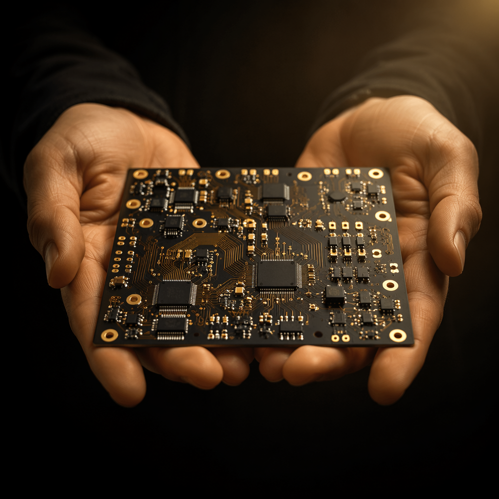
A high-temperature operating life test runs for 1,000 hours at 125 °C to 150 °C, often with 50-100 devices biased in parallel on one board. That is a thousand hours of continuous bias at a temperature that sits above the glass transition of ordinary FR-4. The devices under test are usually the expensive part of the experiment; the board is usually treated as a consumable ordered at the last minute.
That is a mistake with a specific cost signature. When an HTOL board fails mid-run — a contact goes open, a leakage path forms, a barrel cracks — the test does not simply stop. It produces data that looks like device failure. Cells that passed 700 hours are reclassified as failures, the failure-analysis team spends weeks chasing a mechanism inside the die that does not exist, and the run is repeated from hour zero. The board that cost a few hundred dollars has just cost a thousand hours of chamber time and a qualification schedule slip.
This page covers what a board must withstand, the laminate and contact choices that decide it, and the pre-test qualification that finds the boards which would have failed in week five.
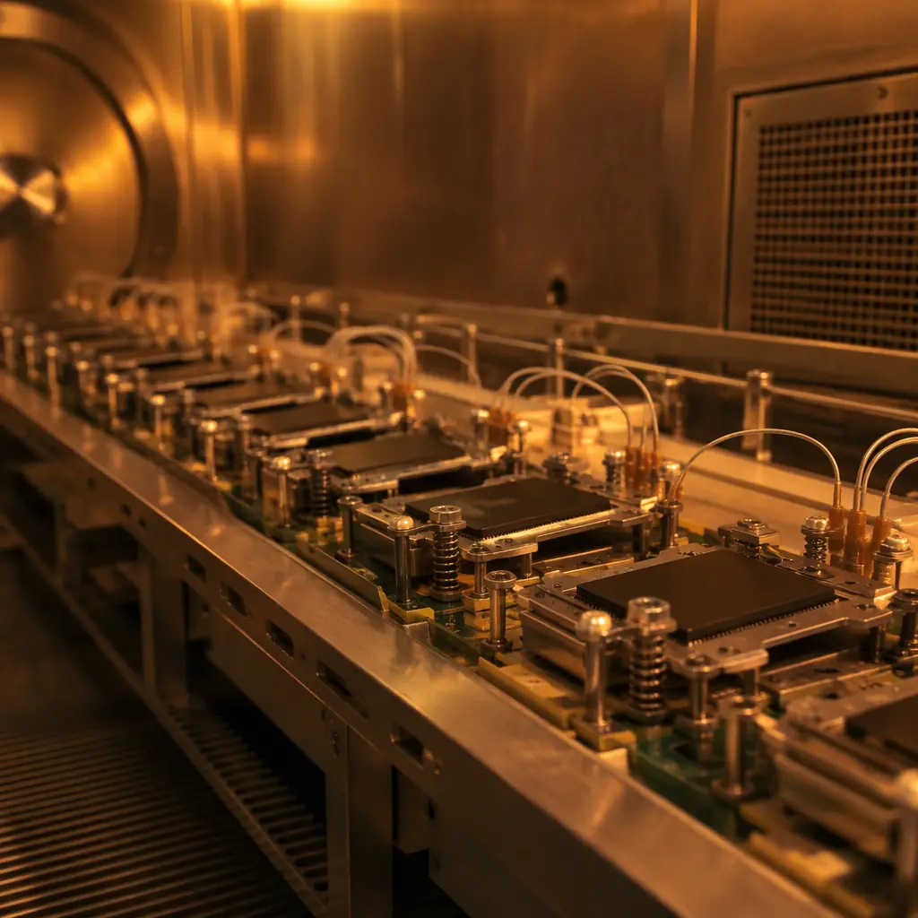
What an HTOL Board Has to Survive
Five simultaneous stressors, and the board has to keep the measurement valid through all of them.
Continuous temperature. 125 °C is the common automotive grade; 150 °C is used for extended qualification and for die-level studies. Chamber temperature is controlled; board temperature is not, because the biased devices dissipate power and sit in still air. Local board temperature at the sockets routinely runs 5-15 °C above chamber setpoint, which is why the effective requirement is the local temperature, not the setpoint on the recipe.
Continuous bias. Rails are held at operating voltage for the full run, often with elevated VDD to accelerate. That means the board carries continuous current through planes and traces for a thousand hours, and any marginal plating defect in a via becomes an electromigration and thermal-cycling test target.
Repeated thermal transitions. Chamber ramps, power cycles, and periodic readouts subject the board to thermal excursions. Even a modest number of cycles accumulates CTE-mismatch stress at every plated through hole and at every socket solder joint.
Contact stability. Socket contacts carry bias current for 1,000 hours at temperature. Contact resistance rises with oxidation, creep and fretting, and it rises unevenly across 100+ sockets. A drift of even 5 Ω in a sensing path changes the measured device behaviour.
Measurement integrity. The board is a measurement instrument as well as a carrier. Leakage paths that form at temperature — flux residue, dendrite growth, surface contamination — create currents that compete with the device leakage being measured. At 150 °C, a 100 nA leakage change is a meaningful device result, and a contaminated board can produce it by itself.
None of these are exotic. Each has a design and fabrication response, and the responses interact: the laminate choice made for the temperature ceiling determines the CTE that drives plated-hole stress, which determines whether the barrels survive the transitions.
What Is an HTOL Board and What Does It Have to Withstand?
Short answer, for the search snippet: An HTOL (high-temperature operating life) board carries biased devices through 1,000 hours at 125 °C to 150 °C and must withstand: laminate stability above its glass transition temperature, CTE-matched plated through holes, socket contact resistance drift below the measurement budget, leakage paths from flux residue and contamination, and continuous bias current through planes and vias for the full duration. Board-level failure in an HTOL run is usually misdiagnosed as device failure.
The specification that governs the test itself is JESD22-A108 for the operating-life methodology; the board is not specified there, which is exactly why board requirements tend to be under-defined and why the numbers below have to come from the buyer rather than the standard.
Laminate Selection: Tg, CTE and the 150°C Ceiling
Glass transition temperature is the first filter. Above Tg, a laminate's CTE in the Z axis roughly triples, the modulus drops, and the plated through holes start seeing expansion they were not designed for. The rule of thumb for boards that must survive repeated excursion above a temperature is that Tg should clear it by 25-40 °C.
| Laminate Class | Tg | Z-Axis CTE below Tg | Z-Axis CTE above Tg | Suited To |
|---|---|---|---|---|
| Standard FR-4 (Tg 130-140 °C) | 130-140 °C | 45-60 ppm/°C | 200-300 ppm/°C | Burn-in at ≤105 °C only |
| Mid-Tg FR-4 (Tg 150-160 °C) | 150-160 °C | 40-50 ppm/°C | 180-250 ppm/°C | HTOL at 125 °C; marginal at 150 °C |
| High-Tg FR-4 (Tg 170-180 °C) | 170-180 °C | 30-45 ppm/°C | 150-200 ppm/°C | HTOL at 125-150 °C; the usual choice |
| High-Tg, low-CTE (Tg 180-200 °C) | 180-200 °C | 25-35 ppm/°C | 120-170 ppm/°C | 150 °C continuous, high layer counts, thick boards |
| Polyimide / BT-epoxy | 200-260 °C | 20-35 ppm/°C | 100-150 ppm/°C | Extended or repeated runs, reuse-critical boards |
Two specific traps sit in this table. The first is quoting Tg alone: two laminates with the same 180 °C Tg can differ by 100 ppm/°C above Tg, and the CTE above Tg is what drives plated-hole barrel stress at 150 °C, where the board spends most of its life. The second is the Td (decomposition temperature) and T-260/T-288 numbers, which describe short-exposure reflow survival rather than thousand-hour service; a laminate that survives three reflow passes at 260 °C is not thereby qualified for continuous 150 °C.
For boards that run repeatedly — HTOL rigs used across multiple qualification programs — the economic case for polyimide or BT is stronger than it looks. A high-Tg FR-4 board that survives one run and delaminates on the second has cost a complete re-run, which is exactly the cost the laminate premium was meant to avoid.
Contact Resistance Drift: The Failure That Invalidates Your Data
Socket contact resistance is the least glamorous and most damaging failure mode on an HTOL board. The contacts sit at temperature under a small bias current for a thousand hours, in an environment with no wiping motion and no cleaning. Three mechanisms drive resistance up:
| Mechanism | What Happens at Temperature | Typical Drift Over 1,000 h | Detection Method |
|---|---|---|---|
| Oxide growth on contact surfaces | Tin or brass contacts oxidise; contact area declines | 5-30 mΩ per contact | Per-contact resistance measurement at temperature |
| Stress relaxation / creep | Spring force decays; contact pressure falls | Equivalent to 10-50 mΩ once pressure drops below threshold | Post-run spring-force or insertion-force check |
| Fretting at micro-motion sites | Thermal cycling moves the contact against the lead; debris builds | Highly variable; can be step changes of 100 mΩ+ | Continuous in-situ monitoring of every cell |
The drift itself is manageable; the problem is whether you know it happened. Without per-cell in-situ monitoring, the standard HTOL practice of periodic readouts at room temperature will measure a board that has cooled and re-established contact, missing the hot-state resistance entirely. A cell that reads 12 mΩ of contact resistance at 150 °C and 2 mΩ at 25 °C will produce hot-state measurements that look like degraded device performance and room-temperature readouts that look fine.
The design response is to make contact resistance observable: Kelvin (four-wire) connections to each DUT position where the measurement budget requires it, a reference resistor per cell to normalise board-level drift, and a per-cell measurement channel that logs at temperature. Boards that share a single sense line across a group of cells cannot attribute drift to a socket, a trace or a device, and that ambiguity is what turns a board problem into a months-long failure analysis.
The remaining insulation side is equally important and frequently overlooked: at 150 °C, flux residue that was benign at room temperature becomes conductive, and ionic contamination from board fabrication becomes a leakage path. Our ionic contamination and cleanliness testing guide covers the measurement (per IPC-TM-650 method 2.3.25) and the cleanliness grades to specify; for HTOL boards, the required grade is stricter than for a standard assembly because the leakage budget is part of the measurement.
Leakage Budget and Bias Integrity at Temperature
The leakage budget is what determines the board's insulation requirements, and it should be derived, not assumed. A worked approach:
| Budget Item | Typical Allocation | Driven By | Specification Lever |
|---|---|---|---|
| DUT leakage (measurement of interest) | Device datasheet value | The device | — |
| Board surface leakage (per cell) | ≤10% of DUT leakage | Contamination, humidity, flux residue | Cleanliness grade, coating, guard traces |
| Board bulk leakage (per cell) | ≤5% of DUT leakage | Laminate resistivity at temperature | Laminate class, layer spacing |
| Socket leakage | ≤5% of DUT leakage | Insulation material in socket body | Socket material rating (often the limit) |
| Residual (allocation for drift) | ~15% | Ageing over 1,000 h | Guard traces, Kelvin sensing, reference cell |
Two design levers follow. Guard traces held at the measurement guard potential around the sense node reduce surface leakage by an order of magnitude at negligible cost, provided they are on both sides and stitched. And a reference cell — an identical socket position with a fixed resistor in place of a DUT — gives a continuous baseline of board-level drift that can be subtracted from every measurement. Both are layout decisions; neither can be added after the board is fabricated.
Bias integrity is the other half. Rails that sag at temperature, or that vary between cells because of trace resistance, introduce a stress variation across the board that changes the acceleration factor cell by cell. That makes the survival statistics harder to interpret, and on a 1,000-hour run with a small sample it can be the difference between a clean Weibull fit and an unusable data set. The practical requirement is a bias distribution measurement at temperature across the board — not at the supply terminals.
Pre-HTOL Board Qualification: IST vs Thermal Shock
The boards that will fail in week five are usually detectable before the run starts. Two accelerated methods find them in days rather than months.
| Method | What It Stresses | Cycle Count / Duration | Detects |
|---|---|---|---|
| IST (Interconnect Stress Test) | Direct Joule heating of the plated hole, rapid ramp | 150 cycles typically, ~6 hours | Plated barrel integrity, laminate CTE mismatch, plating ductility |
| Thermal shock (air-to-air, e.g. IPC-9701 / JESD22-A104) | Chamber-ramp thermal cycling of the whole assembly | 100-1,000 cycles depending on severity | Solder joint fatigue, CTE-driven barrel stress, socket joint integrity |
| Bias burn-in at 150 °C (short) | Temperature plus bias, no device installed | 48-168 hours | Laminate stability, leakage formation, contact drift onset |
IST is the higher-yield screen for the plated-hole risk specifically: it drives current directly through the barrel, so the thermal excursion inside the hole is much larger than a chamber ramp produces, and resistance change is measured continuously on the same structure that will carry bias for a thousand hours. The comparison between IST and thermal shock, including when each is the right screen, is covered in IST vs thermal shock for via reliability; thermal cycling test specifications and acceptance criteria are in PCB thermal cycling testing.
Practical sequencing for an HTOL board: IST on a coupon or a sacrificial test panel from the same lot, a short unpopulated bias bake at the target temperature to verify laminate and leakage, then assembly and socket installation, then the full run. The IST result is the go/no-go that protects the thousand hours.
The Cost of a Failed HTOL Run and the Board Spec That Prevents It
The arithmetic that justifies an expensive HTOL board is simple and rarely done explicitly.
| Item | Typical Cost | Notes |
|---|---|---|
| HTOL board (high-Tg, 4-8 layers, socketed, Kelvin sensing) | USD 400-1,500 | Higher for 150 °C continuous or 100+ positions |
| Assembly and socket installation | USD 300-900 | Socket hardware often the dominant part of this line |
| 1,000 hours of chamber time, 100-position board | USD 8,000-25,000 | Chamber, power, monitoring labour, engineering |
| Failure analysis of 3-8 "failed" cells | USD 5,000-20,000 | Includes decapsulation, cross-section, SEM, report |
| Schedule slip to requalification | weeks to months | Usually the largest line, and the one nobody costs |
A board upgrade from mid-Tg FR-4 to a high-Tg, low-CTE laminate with proper Kelvin sensing and a reference cell costs a few hundred dollars. A single invalidated run costs at least five figures in chamber and analysis time, before the schedule. The board is 2-5% of the run cost and it governs the validity of 100% of the data.
Four specifications protect the run, and all four belong on the board purchase order rather than in an email:
1. Laminate, by Tg and CTE above Tg, with the laminate part number named. Not "high Tg FR-4"; the specific material, so it can be re-verified on a later order.
2. Cleanliness grade and ionic contamination limit. Stated as a measured value with the test method, since the leakage budget depends on it.
3. Per-cell Kelvin sensing and a reference cell, stated as layout requirements with a defined measurement channel count.
4. IST or thermal-shock qualification per lot, with accept criteria. This is the line that converts a board specification into a screen, and it is the one that catches the failing lots before the chamber is booked.
The same discipline applies to the burn-in and load-board family more broadly — socket wear, load-board mechanical spec and handling are covered in burn-in board and load board specification, and the broader thermal-aging context is in HTOL and thermal aging for PCB assemblies.