
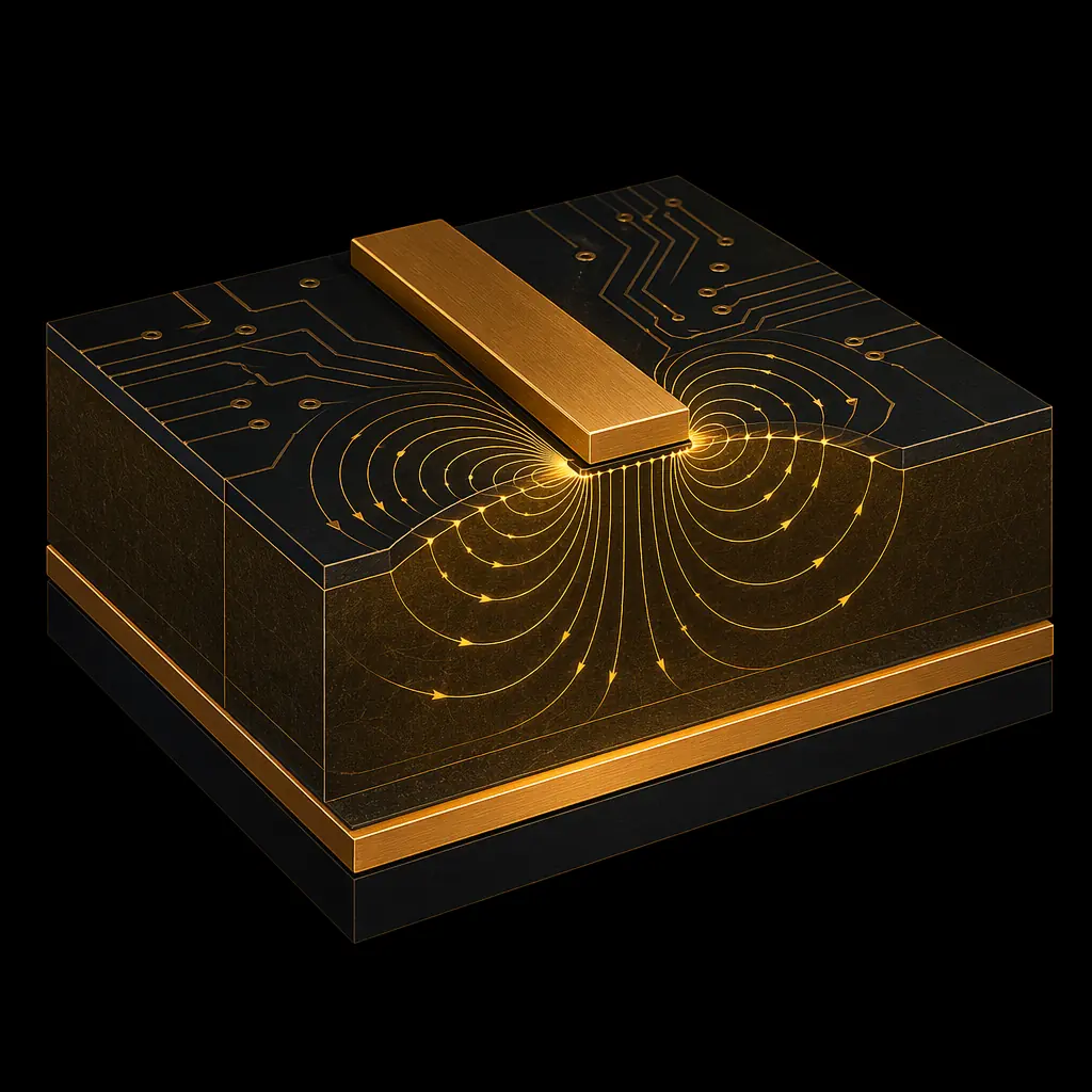
PCB Fabrication / Impedance Control
Precision controlled impedance for high-speed digital, RF, and mixed-signal designs. Every controlled-impedance panel is TDR-verified with a full test report. Target 50 single-ended, 90/100 differential, with tolerances as tight as 5%.
Why Impedance Matters
At frequencies above 50 MHz, PCB traces behave as transmission lines. Mismatched impedance causes signal reflections, ringing, crosstalk, and bit errors. Controlled-impedance PCB design ensures that every high-speed signal sees a consistent characteristic impedance along its entire path, from driver to receiver. Our engineering team calculates trace width, spacing, and dielectric thickness for each controlled-impedance layer, then verifies every panel with TDR measurement.
Tolerance Options
Suitable for most digital interfaces at moderate speeds, DDR3, USB 2.0, HDMI 1.4, and general controlled-impedance designs where some margin exists.
Recommended for DDR4, USB 3.0/3.1, PCIe Gen3/4, HDMI 2.0, and SATA III. Tighter control reduces eye diagram closure at higher data rates.
Required for PCIe Gen5, 100GBASE-KR4, 5G NR front-end, mmWave RF, and DDR5. Demands high-performance laminates and rigorous TDR correlation.
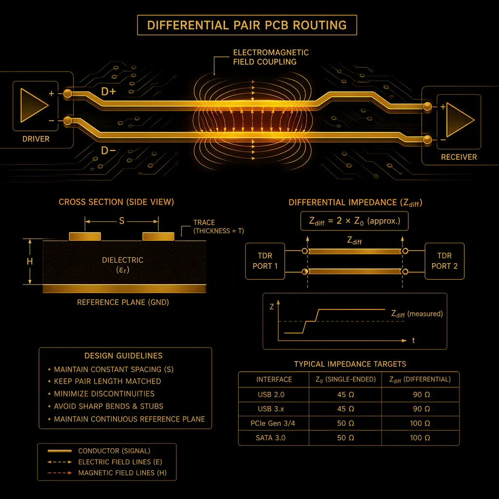
One signal trace referenced to a ground plane. Most common impedance target for RF and general high-speed traces.
Two coupled traces carrying complementary signals. Superior noise immunity and common-mode rejection for high-speed data.
TDR Verification
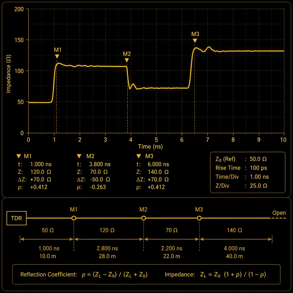
TDR (Time Domain Reflectometry) sends a fast-rise-time pulse down a test coupon trace and measures reflections. Any impedance variation shows as a deviation in the reflected waveform. We place impedance test coupons on every controlled-impedance panel, test each coupon, and provide a detailed TDR report with your shipment. Typical coupon length: 150mm (6 inches) with SMA or probe-pad launch structures.
| Material | Dk @ 1GHz | Df @ 1GHz | Best Impedance Tolerance | Typical Applications |
|---|---|---|---|---|
| FR-4 High-Tg (Tg 170) | 4.2-4.6 | 0.018-0.022 | ±7-10% | DDR3/4, USB 3.0, HDMI 1.4, general digital |
| FR-4 Mid-Dk (EMC EM-825) | 3.8-4.0 | 0.012-0.015 | ±7% | PCIe Gen3/4, SATA III, 10G Ethernet |
| Panasonic Megtron 6 | 3.5-3.7 | 0.002-0.004 | ±5% | PCIe Gen5, 100G/400G, 5G backhaul, 112G PAM4 |
| Rogers 4350B | 3.48 ±0.05 | 0.0037 | ±5% | RF power amplifiers, antennas, 5G NR, satellite |
| Rogers 4003C | 3.38 ±0.05 | 0.0027 | ±5% | Radar, mmWave, aerospace RF, low-loss applications |
| PTFE (Taconic RF-35) | 3.5 | 0.0018 | ±5% | mmWave 24-77GHz, satellite transceivers, T/R modules |
| Hybrid: FR-4 + Rogers | Mixed | Mixed | ±5-7% | RF+digital mixed-signal, cost-optimized RF boards |
Send us your target impedance values and layer count. Our engineering team will design a stackup with exact trace widths, spacings, and dielectric thicknesses, then TDR-verify every panel. Free stackup consultation included.
Upload Gerber + BOM, 24h quote with free DFM review.