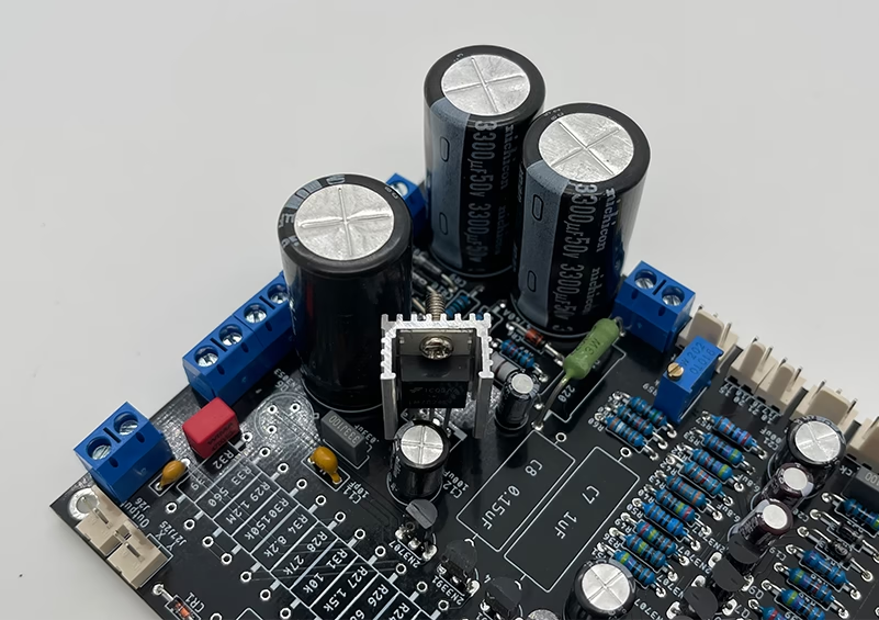
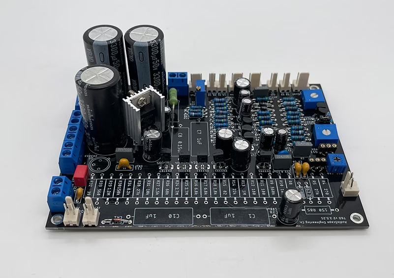
Have you ever wondered how bulky electronic components in industrial machinery or automotive systems achieve decades of reliable performance? Dual In-line Package (DIP) PCB assembly, a foundational technology since the 1960s, remains indispensable for high-durability applications despite the rise of surface-mount technology (SMT). This guide explores how DIP assembly bridges traditional through-hole techniques with modern manufacturing demands.
Why DIP Assembly Still Matters in Modern Electronics?
While SMT dominates consumer electronics, DIP assembly persists in critical sectors due to three irreplaceable strengths:
- Mechanical Robustness
DIP components with through-hole leads withstand 5X higher vibration stress than SMT parts, per MIL-STD-883 testing standards. This makes them ideal for automotive control units and aerospace systems. - Thermal Endurance
Components like power relays in DIP packages tolerate temperatures up to 125°C, outperforming SMT equivalents by 30% in high-heat environments. - Simplified Prototyping
Engineers favor DIP for R&D due to manual adjustability—a 2024 industry survey showed 68% of industrial automation prototypes still use DIP layouts.
The DIP Assembly Process: Precision Meets Durability
Stage 1: Component Preparation
- Lead Trimming: Automated machines cut component leads to 2.3±0.2mm lengths for optimal solder penetration.
- Pre-bending: 45° angle adjustments prevent tombstoning during wave soldering.
Stage 2: Manual/Automated Insertion
- Hand Insertion: Skilled technicians achieve <0.01% misalignment in low-volume batches.
- Auto-Insertion: Machines like Panasonic AVK series handle 12,000 components/hour with 25μm precision.
Stage 3: Wave Soldering Optimization
A 5-zone thermal profile ensures flawless joints:
| Zone | Temperature | Function |
|---|---|---|
| 1-2 | 150-170°C | Flux activation |
| 3 | 190-210°C | Preheat stabilization |
| 4-5 | 240-260°C | Solder wave contact |
This process creates joints with <15% void rates, exceeding IPC-A-610 Class 2 standards.

Key Advantages Over Alternative Technologies
1. Military-Grade Reliability
DIP assemblies maintain functionality after:
- 50G mechanical shock impacts (per MIL-STD-202)
- 1,000-hour salt spray tests (ASTM B117)
- -55°C to +125°C thermal cycling
2. Cross-Platform Compatibility
- Direct integration with legacy systems using 2.54mm pitch standards
- Mixed-technology PCBs combining DIP and SMT components
3. Cost Efficiency for Niche Applications
- 40% lower tooling costs vs. fine-pitch SMT for small batches
- Simplified rework: Component replacement takes 2-3 minutes vs. 15+ minutes for BGA reballing
Quality Control Protocols
4-Point Inspection System
- Pre-Solder Verification
AOI systems detect insertion errors with 20MP cameras (≤3μm resolution). - Post-Solder Analysis
X-ray imaging identifies hidden defects like:
• Solder cracks (<25μm width)
• Insufficient fill (<75% hole coverage) - Functional Testing
In-circuit testers validate 100% electrical continuity at 50mA resolution. - Environmental Stress Screening
48-hour burn-in tests at 85°C/85% RH weed out infant mortality failures.

Industry Applications Driving Demand
Automotive Electronics
- Engine control modules requiring 15-year service life
- ABS sensor interfaces with IP69K waterproofing
Industrial Control Systems
- PLC I/O boards resisting EMI up to 100V/m
- High-voltage contactors (up to 480V AC)
Medical Equipment
- MRI machine power supplies needing <1ppm lead-free alloys
- Sterilizable surgical tool controllers
DIP PCB assembly continues enabling mission-critical systems where failure isn’t an option. Its unique blend of mechanical stability and electrical performance ensures ongoing relevance across industries pushing the boundaries of durability.
For expert guidance on implementing DIP solutions, contact me at sales@huaxingpcba.com. We specialize in bridging robust through-hole reliability with cutting-edge manufacturing innovations.


